
Stratus L4-2.0L VIN C (1997)
If available, an oscilloscope can display the square wave patterns of each voltage pulse. From the frequency of the output voltage pulses, the PCM
calculates engine speed. The width of the pulses represent the amount of time the output voltage stays high before switching back to low. The
period of time the sensor output voltage stays high before switching back to low is referred to as pulse-width. The faster the engine is operating,
the smaller the pulse-width on the oscilloscope.
By counting the pulses and referencing the pulse from the 60° signature notch, the PCM calculates crankshaft angle (position). In each group of
timing reference notches, the first notch represents 69° Before Top Dead Center (BTDC). The second notch represents 49° BTDC. The third
notch represents 29°. The last notch in each set represents 9° Before Top Dead Center (TDC).
The timing reference notches are machined at 20° increments. From the voltage pulse-width the PCM tells the difference between the timing
reference notches and the 60° signature notch. The 60° signature notch produces a longer pulse-width than the smaller timing reference notches. If
the camshaft position sensor input switches from high to low when the 60° signature notch passes under the crankshaft position sensor, the PCM
knows cylinder number one is the next cylinder at TDC.
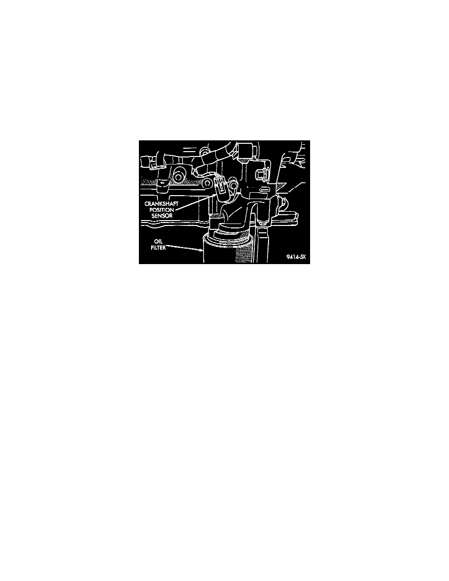
Fig. 7 Crankshaft Position Sensor
The crankshaft position sensor attaches to the cowl side of the engine block. It is located between the main bearing cap/bed plate assembly and
block behind the power steering pump Fig. 7.
CIRCUIT OPERATION
Circuit K7 supplies 8 volts from the Powertrain Control Module (PCM) to the crankshaft position sensor. The K7 circuit connects to cavity 44 of
the PCM.
Circuit K24 from the sensor provides an input signal to the PCM. The K24 circuit connects to cavity 32 of the PCM. On automatic transmission
vehicles this circuit is spliced and provides an input to the Transmission Control Module (TCM).
The PCM provides a ground for the crankshaft position sensor signal (circuit K24) through circuit K4. Circuit K4 connects to cavity 43 of the
PCM connector.
HELPFUL INFORMATION
The K7 circuit is spliced and provides 8 volts for the camshaft position sensor and the vehicle speed sensor (manual transmission only).