
Stratus L4-2.4L DOHC (1995)
Coolant Temperature Sensor/Switch (For Computer): Component Tests and General Diagnostics
Component Testing
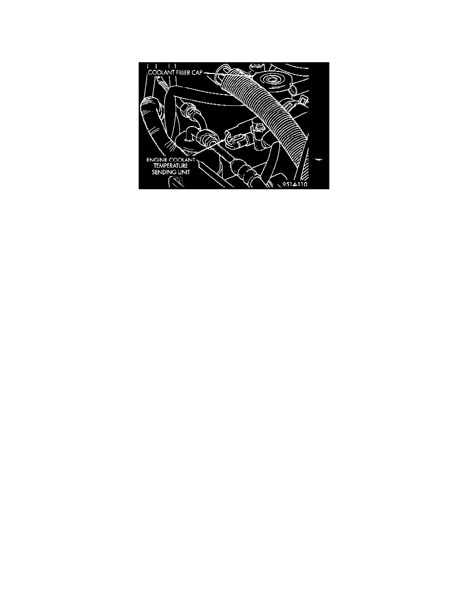
Fig. 17 Engine Coolant Temperature Sensor
To perform a complete test of this sensor and its circuitry, refer to DRB scan tool and appropriate Computers and Control Systems/System
Diagnosis/Diagnostic Charts.
To test the sensor only, refer to the following:
1. With the key off, disconnect wire harness connector from coolant temperature sensor.
2. Connect one lead of a high input impedance (digital) volt-ohmmeter to one terminal of sensor.
3. Connect the other ohmmeter lead to remaining terminal of sensor. The ohmmeter should read as follows:
^
Engine/Sensor at normal operating temperature around 200°F should read approximately 700 to 1,000 ohms.
^
Engine/Sensor at room temperature around 70°F ohmmeter should read approximately 7,000 to 13,000 ohms.
4. Test the resistance of the wire harness between the PCM connector terminal 26 and the sensor harness connector. Also check for continuity
between connector terminal 43 and the sensor harness connector. Refer to Diagrams/Electrical for circuit information. If the resistance is greater
than 1 ohm, repair the wire harness as necessary.
Helpful Information
Circuit K4 splices to supply ground for the signals from the following:
-
Intake air temperature sensor
-
Camshaft position sensor
-
Manifold absolute pressure sensor
-
Throttle position sensor
-
A/C pressure switch
-
Crankshaft position sensor
-
Vehicle speed sensor
-
Heated oxygen sensors