
Stratus L4-2.4L VIN X (1998)
Ignition Coil: Testing and Inspection
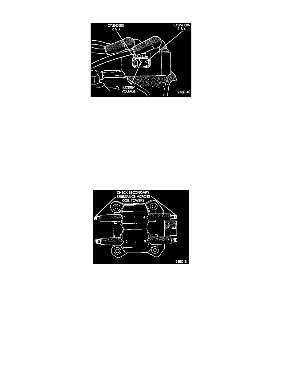
Fig. 2 Terminal Identification
NOTE: Coil one fires cylinders 1 and 4, coil two fires cylinders 2 and 3. Each coil tower is labeled with the number of the corresponding cylinder.
1. Remove the ignition cables and measure the resistance of the cables. Resistance must be in this range:
Coil Resistance @ 21-27°C (70-80°F)
-
Primary
0.51 to 0.61 ohms
-
Secondary
11,500 to 13,500 ohms
Replace any cable not within tolerance.
2. Disconnect the electrical connector from the coil pack.
3. Measure the primary resistance of each coil. At the coil, connect an ohmmeter between the B+ pin and the pin corresponding to the cylinders in
question Fig. 2. Resistance on the primary side of each coil should be 0.45 - 0.65 ohm @ 70° - 80° F. Replace the coil if resistance is not within
tolerance.
Fig. 3 Checking Ignition Coil Secondary Resistance
4. Remove ignition cables from the secondary towers of the coil. Measure the secondary resistance of the coil between the towers of each individual
coil Fig. 3. Secondary resistance should be 7,000 to 15,800 ohms. Replace the coil if resistance is not within tolerance.