
Stratus V6-2.5L VIN H (1997)
^
Braking surface scoring, rust, impregnation of lining material and worn ridges.
^
Excessive lateral runout or wobble.
^
Thickness variation (Parallelism).
^
Dishing or distortion (Flatness).
If a vehicle has not been driven for a period of time, the rotor surface will rust in the area not covered by the brake lining and cause noise and
chatter when the brakes are applied. Excessive wear and scoring of the rotor can cause temporary improper lining contact if ridges are not removed
before installation of new brake pad assemblies. Some discoloration or wear of the rotor surface is normal and does not require resurfacing when
linings are replaced. Excessive runout or wobble in a rotor can increase pedal travel due to piston knock back. This will increase guide pin sleeve
wear due to tendency of caliper to follow rotor wobble. Thickness variation in a rotor can also result in pedal pulsation, chatter and surge due to
variation in brake output. This can also be caused by excessive runout in rotor or hub. Dishing or distortion can be caused by extreme heat and
abuse of the brakes.
RUNOUT
On vehicle rotor runout is the combination of the individual runout of the hub face and the runout of the rotor. (The hub and rotor runouts are
separable). To measure runout on the vehicle, remove the wheel and reinstall the lug nuts tightening the rotor to the hub. Mount Dial Indicator,
Special Tool C-3339 with Mounting Adapter, Special Tool SP-1910, or equivalents on steering arm. Dial indicator plunger should contact braking
surface of rotor approximately one inch from edge of rotor. Check lateral runout (both sides of rotor) runout should not exceed 0.13 mm (0.005
inch). If runout is in excess of the specification, check the lateral runout of the hub face. Before removing rotor from hub, make a chalk mark
across both the rotor and one wheel stud on the high side of runout so you'll know exactly how the rotor and hub was originally mounted. Remove
rotor from hub. Install Dial Indicator, Special Tool C-3339 and Mounting Adapter, Special Tool SP- 1910, or equivalents on steering knuckle.
Position stem so it contacts hub face near outer diameter. Care must be taken to position stem outside the stud circle but inside the chamfer on the
hub rim. Clean hub surface before checking. Runout should not exceed 0.08 mm (0.003 inch). If runout exceeds this specification, hub must be
replaced. Refer to Steering and Suspension. If hub runout does not exceed this specification, install rotor on hub with chalk marks two wheel studs
apart. Tighten nuts in the proper sequence and torque to specifications. Finally, check runout of rotor to see if runout is now within specifications.
If runout is not within specifications, install a new rotor or reface rotor, being careful to remove as little as possible from each side of rotor.
Remove equal amounts from each side of rotor. Do not reduce thickness below minimum thickness cast into the unmachined surface of the rotor.
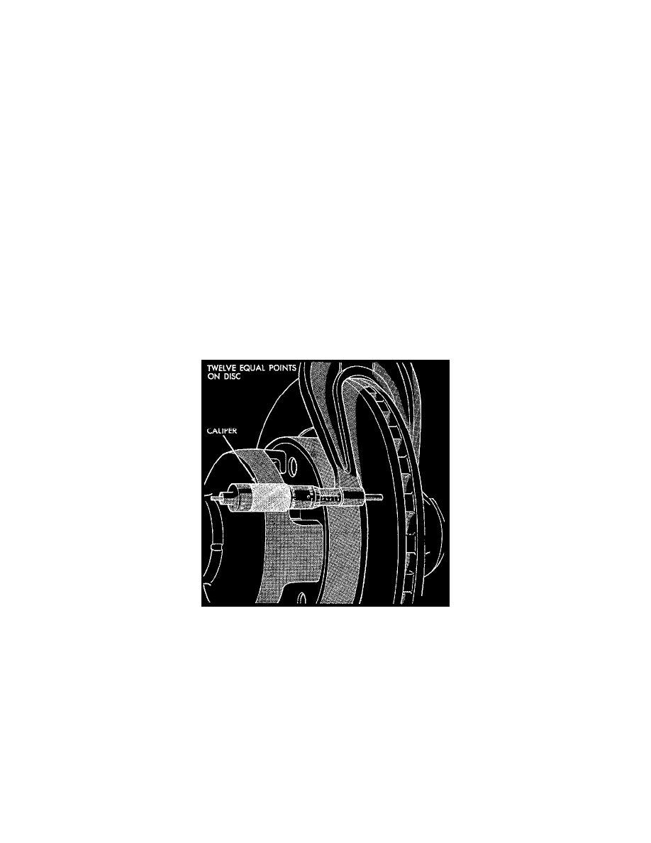
Checking Rotor For Thickness Variation
THICKNESS VARIATION
Thickness variation measurements of rotor should be made in conjunction with runout. Measure thickness of rotor at 12 equal points with a
micrometer at a radius approximately 25 mm (1 inch) from edge of rotor. If thickness measurements vary by more than 0.013 mm (0.0005 inch)
rotor should be removed and resurfaced, or a new rotor installed. If cracks or burned spots are evident, rotor must be replaced. Light scoring
and/or wear is acceptable. If heavy scoring or warping is evident, the rotor must be machined or replaced.