
Stratus V6-2.5L VIN H (1997)
Brake Proportioning/Combination Valve: Description and Operation
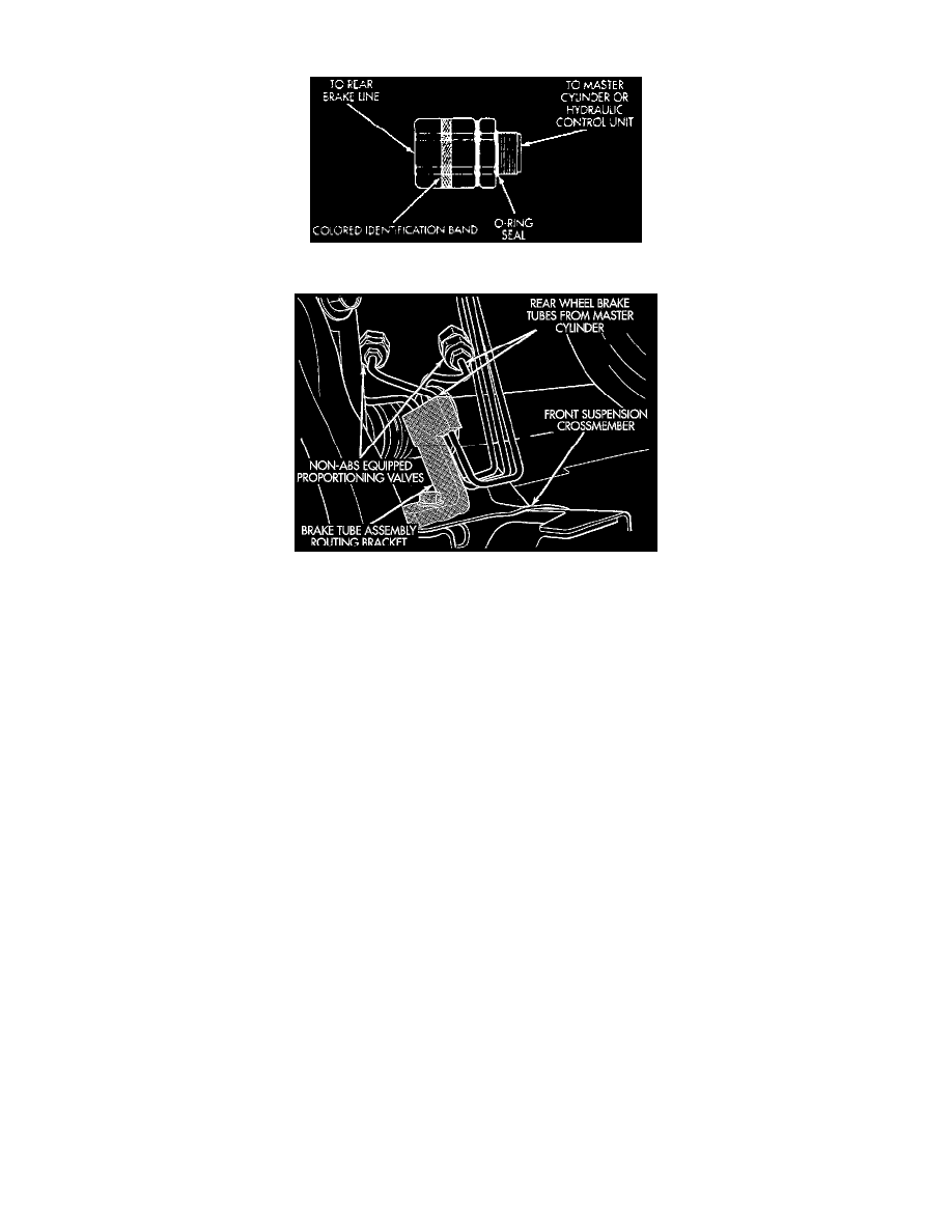
Fig 35 Type 3 Proportioning Valve Identification
Proportioning Valves For Non-ABS Vehicles
GENERAL INFORMATION
This vehicle is available with two different master cylinder assemblies. This vehicle uses screw-in proportioning valves in-line with the rear brake
tubes on vehicles not equipped with Antilock Brakes. On vehicles equipped with the Allied Signal ABX-4 Antilock Brake system, the
proportioning valves are located at the rear brake outlet ports of the Hydraulic Control Unit (HCU). The Proportioning Valve can be identified by
the bar code label and stamp on the Proportioning Valve. Be sure replacement Proportioning Valve has the same stamp as the Proportioning Valve
being replaced.
These new in-line proportioning valves used on this vehicle replace the combination valve used in prior designs. With this new design, the chassis
brake tubes connect directly from the master cylinder or HCU to the brake flex hose. Vehicles not equipped with ABS use a master cylinder
incorporating the standard type compensating port design. Vehicles which are equipped with ABS use a master cylinder having a center valve
design. In addition, the ABS master cylinder is a 2 outlet port design and the non-ABS master cylinder is a four outlet design. The non-ABS brake
system uses two screw-in proportioning valves attached directly in-line with the rear brake tubes. The non-ABS equipped proportioning valves are
located in the same area of the vehicle as the hydraulic unit on ABS equipped vehicles.
FUNCTION
Proportioning valves balance front to rear braking by controlling at a given ratio, the increase in rear brake system hydraulic pressure above a
preset level (split point). Under light pedal application, the proportioning valve allows full hydraulic pressure to. be applied to the rear brakes.
IDENTIFICATION
There are two proportioning valve assemblies used in each vehicle. Due to differences in thread sizes, each proportioning valve has a different part
number. During any service procedures identify valve assemblies by supplier part number and or the bar code label and stamp identification band.
All vehicle brake systems use a common calibration for the proportioning valve. The split point is 500 psi and the slope is 0.43.