
Stratus V6-2.5L VIN H (1997)
Control Module HVAC: Description and Operation
SYSTEM OPERATION
HVAC Control Module
HVAC Control Module
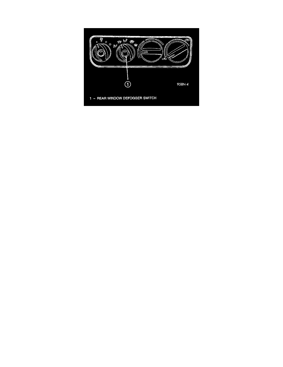
The rear window control switch and circuit are integrated into the HVAC control module. When actuating the switch it sends a ground signal to
the Body Control Module (BCM). The BCM actuates the relay allowing current to flow through the grid lines for ten minutes upon initial
actuation. Then 5 minutes with each subsequent actuation or until either the switch or ignition is turned off. An indicating lamp illuminates the
rear window defogger switch.
CIRCUIT OPERATION
A/C - Heater Control
The air conditioning-heater system is controlled by the Body Control Module (BCM). The BCM sends out voltage to the A/C-Heater control on
circuit C58. The control uses resistors to internal to the control. These resistors are connected to the Z2 ground circuit.
When the operator requests a function in the system the BCM measures the voltage drop, on circuit C58, and activates the mode actuator door to
the proper position.
A separate A/C switch is used in the system. This switch works the same as the mode actuator switches. When the operator presses the switch the
BCM measures the voltage drop in the C21 circuit and activates the proper functions. Internal to the A/C-Heater control the A/C switch is
connected to the blower motor switch. This allows the A/C system to only operate when the blower switch in an ON position.
Ground for the A/C switch is provided through the blower motor switch to the Z1 circuit. This circuit terminates at the instrument panel left side
cowl. A Light Emitting Diode (LED) is connected in the C21 circuit and illuminates when the A/C system is operating.
Illumination lamps and LED's are internal to the control. These are controlled by the BCM. The E2 circuit from the BCM provides the voltage to
the control for lamp and LED illumination. Ground for the lamps and LED's is provided on the Z1 circuit which terminates at the instrument panel
left side cowl.