
Stratus Coupe L4-2.4L VIN G (2003)
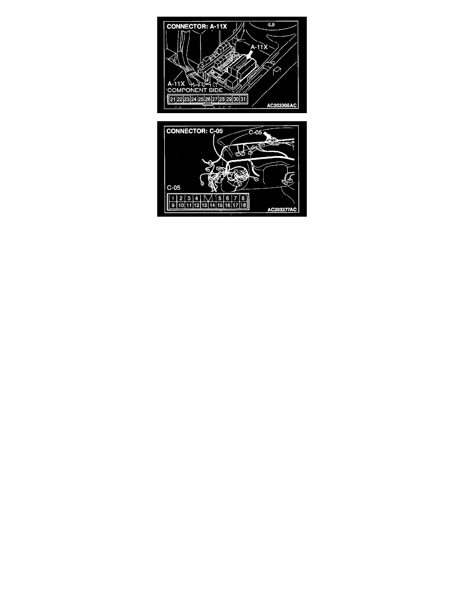
STEP 6. Check the wiring harness between windshield wiper motor connector A-03 (terminal 4) and front-ECU connector A-11X (terminal 23).
NOTE: Also check intermediate connector C-05 for loose, corroded, or damaged terminals, or terminals pushed back in the connector. If intermediate
connector C-05 is damaged, repair or replace the damaged components) as described in Harness Connector Inspection.
Q: Is the wiring harness between windshield wiper motor connector A-03 (terminal 4) and front-ECU connector A-11X (terminal 23) in good
condition?
YES : Replace the front-ECU. The windshield wiper should stop at the predetermined park position.
NO : The wiring harness may be damaged or the connector(s) may have loose, corroded or damaged terminals, or terminals pushed back in the
connector. Repair the wiring harness as necessary. The windshield wiper should now stop at the predetermined park position.
Inspection Procedure G-4
INSPECTION PROCEDURE G-4: Windshield Wiper and Washer: Windshield intermittent wiper interval cannot be adjusted.
TECHNICAL DESCRIPTION (COMMENT)
The ETACS-ECU calculates the intermittent wiper interval from the following input signals, and sends a signal to the front-ECU through the SWS
communication line.
If the signal is defective, the front-ECU will ignore the signal and set the intermittent wiper interval to four seconds.
TROUBLESHOOTING HINTS
-
The column switch (windshield wiper and washer switch) may be defective.
-
The ETACS-ECU may be defective.
-
The front-ECU may be defective.
-
The wiring harness or connectors may have loose, corroded or damaged terminals, or terminals pushed back in the connector.
DIAGNOSIS
Required Special Tools:
-
MB991223: Test Harness Set
-
MB991502: Scan Tool (MUT-II)
-
MB991529: Diagnostic Trouble Code Check Harness
STEP 1. Check method of the input signal
Q: Which is to be used, the scan tool or a voltmeter to check the input signal?
Scan tool MB991502 : Go to Step 2.
Voltmeter : Go to Step 3.