
Stratus Coupe L4-2.4L VIN G (2003)
Alignment: Specifications
Front
FRONT WHEEL ALIGNMENT CHECK AND ADJUSTMENT
Required Special Tool:
- MB991004: Wheel Alignment Gauge Attachment.
Measure wheel alignment with alignment equipment on a level surface. The front suspension, steering system, and wheels should be serviced to
normal condition before measuring wheel alignment.
TOE-IN
Standard value: 0 ± 3 mm (0 ± 0.12 inch)
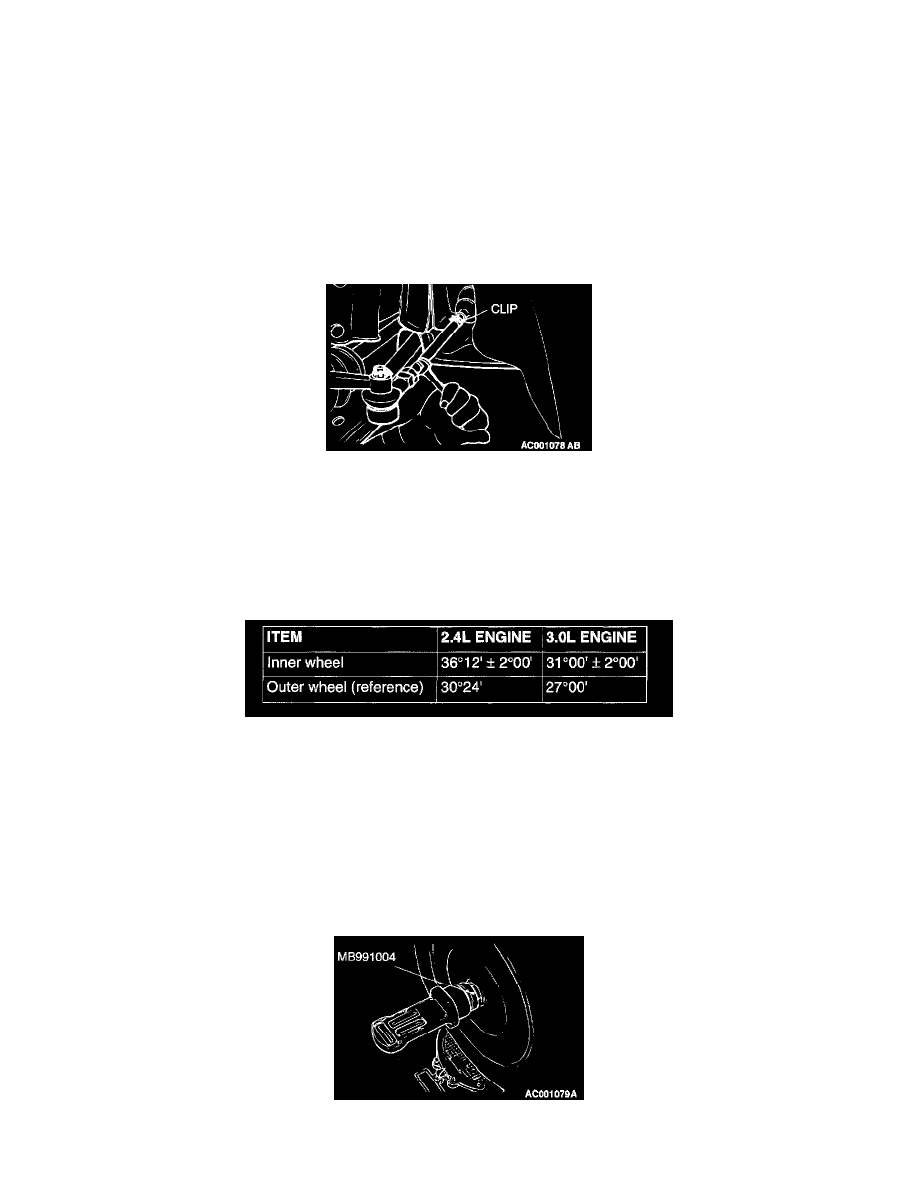
1. Adjust the toe-in by undoing the clip and turning the left and right tie rod turnbuckles by the same amount (in opposite directions).
NOTE: The toe will move out as the left turnbuckle is turned toward the front of the vehicle and the right turnbuckle is turned toward the rear of
the vehicle.
2. Use a turning radius gauge to check that the steering angle is at the standard value.
STEERING ANGLE
Standard value:
CAMBER AND CASTER
Standard value:
Camber 0 ° 00' ± 30'(Left/right deviation within 30')
Caster 3 ° 00' ± 30'(Left/right deviation within 30')
NOTE: Caster is preset at the factory and cannot be adjusted.
CAUTION: Never subject the wheel bearings to the vehicle load when the driveshaft nuts are loosened.
NOTE: For vehicles with aluminum type wheels, attach the camber/caster/kingpin gauge to the driveshaft by using special tool MB991004. Tighten
special tool MB991004 to the same torque 226 ± 29 Nm (167 ± 21 ft. lbs.) as the driveshaft nut.