
Stratus Coupe V6-3.0L VIN H (2001)
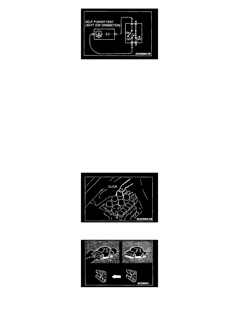
3. CONTINUITY CHECK
1. When the switch is in the "OFF" position, the self-powered test light should illuminate or the ohmmeter should read 0 ohm, only when the
contact points of terminals 1 and 2 are connected.
2. When the switch is the "ON" position, the self-powered test light should come on or the ohmmeter should read 0 ohm, only when the contact
points of terminals 3 and 4 are connected.
Information For Diagnosis
INFORMATION FOR DIAGNOSIS
This information contains the harness diagrams as well as the individual circuit drawings, operational explanations, and troubleshooting hints for each
component. The information is presented in the following manner:
1. Connector diagrams show the connector positions, etc., on the actual vehicle as well as the harness path.
2. Circuit diagrams show the configuration of the circuit with all switches in their normal positions.
3. Operational explanations include circuit drawings of voltage flow when the switch is operated and how the component operates in reaction.
4. Troubleshooting hints include numerous examples of problems which might occur, traced backward in a common-sense manner to the origin of the
trouble. Problems whose origins may not be found in this manner are pursued through the various system circuits.
NOTE: Components of MFI, ETACS, etc. with ECU do not include 3 and 4 above. For this Information, refer to a relevant group which includes details
of these components.
Inspection
INSPECTION
1. Sight and Sound checks
Check relay operation, blower motor rotation, light illumination, etc. Listen for a "click" when a relay cover is pushed down.
2. Simple checks