
Stratus Sedan L4-2.4L VIN X (2003)
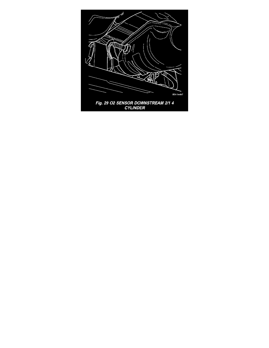
Fig.29 O2 Sensor Downstream 2/1 4 Cylinder
The downstream heated oxygen sensor threads into the outlet pipe at the rear of the catalytic convertor.
For SBEC vehicles a single sensor ground is used for all 4 O2 sensors (6 Cyl.). A separate upstream and downstream grounds are used on the NGC
vehicles (4 Cyl.).
As vehicles accumulate mileage, the catalytic convertor deteriorates. The deterioration results in a less efficient catalyst. To monitor catalytic
convertor deterioration, the fuel injection system uses two heated oxygen sensors. One sensor upstream of the catalytic convertor, one downstream of
the convertor. The PCM compares the reading from the sensors to calculate the catalytic convertor oxygen storage capacity and converter efficiency
Also, the PCM uses the upstream heated oxygen sensor input when adjusting injector pulse width.
When the catalytic converter efficiency drops below emission standards, the PCM stores a diagnostic trouble code and illuminates the malfunction
indicator lamp (MIL).
The O2 sensors produce voltages from 0 to 1 volt (this voltage is offset by a constant 2.5 volts on NGC vehicles), depending upon the oxygen content
of the exhaust gas. When a large amount of oxygen is present (caused by a lean air/fuel mixture, can be caused by misfire and exhaust leaks), the
sensors produces a low voltage. When there is a lesser amount of oxygen present (caused by a rich air/fuel mixture, can be caused by internal engine
problems) it produces a higher voltage. By monitoring the oxygen content and converting it to electrical voltage, the sensors act as a rich-lean switch.
The oxygen sensors are equipped with a heating element that keeps the sensors at proper operating temperature during all operating modes.
Maintaining correct sensor temperature at all times allows the system to enter into closed loop operation sooner. Also, it allows the system to remain in
closed loop operation during periods of extended idle.
In Closed Loop operation the PCM monitors the O2 sensors input (along with other inputs) and adjusts the injector pulse width accordingly. During
Open Loop operation the PCM ignores the O2 sensor input. The PCM adjusts injector pulse width based on preprogrammed (fixed) values and inputs
from other sensors.
1.6L Siemens controller and SBEC controller - The Automatic Shutdown (ASD) relay supplies battery voltage to both the upstream and
downstream heated oxygen sensors. The oxygen sensors are equipped with a heating element. The heating elements reduce the time required for the
sensors to reach operating temperature. The PCM uses pulse width modulation to control the ground side of the heater to regulate the temperature on 4
cyl. upstream O2 heater only.
NGC Controller - Has a common ground for the heater in the O2S. 12 volts is supplied to the heater in the O2S by the NGC controller. Both the
upstream and downstream O2 sensors for NGC are pulse width modulation (PWM).
UPSTREAM OXYGEN SENSOR
The input from the upstream heated oxygen sensor tells the PCM the oxygen content of the exhaust gas. Based on this input, the PCM fine tunes the
air-fuel ratio by adjusting injector pulse width.
The sensor input switches from 0 to 1 volt, depending upon the oxygen content of the exhaust gas in the exhaust manifold (this is offset by 2.5 voltage
on NGC vehicles). When a large amount of oxygen is present (caused by a lean air-fuel mixture), the sensor produces voltage as low as 0.1 volt. When
there is a lesser amount of oxygen present (rich air-fuel mixture) the sensor produces a voltage as high as 1.0 volt. By monitoring the oxygen content
and converting it to electrical voltage, the sensor acts as a rich-lean switch.