
Viper V10-488 8.0L (1992)
Cross-Member: All Technical Service Bulletins
Drive Line - Clunk on Acceleration/Deceleration
NO: 03-04-95
GROUP: Rear Axle
DATE: Jun. 23, 1995
SUBJECT:
Drive Line Tip In/Tip Out Clunk
MODELS:
1992 - 1995 (SR) Viper
SYMPTOM/CONDITION:
Excessive driveline clunk may be noticeable while accelerating and decelerating.
DISCUSSION:
Some driveline backlash is normal and inherent with design of the vehicle. Clearances in the driveline such as gear lash in the rear axle and end play
clearances in the transmission are incorporated in to the design of these components and must be present for component durability. The presence of these
clearances dictate that there will never be the situation where the driveline backlash can be completely eliminated, particularly where this much power is
available. Attempts should not be made to disassemble driveline components to tighten up clearances.
DIAGNOSIS/REPAIR:
1.
Keeping in mind the above statement, road test the vehicle and determine if the clunk is objectionable. If the clunk is determined to be
objectionable, continue through the following steps which have been developed to eliminate known contributors to excessive driveline clunk.
2.
Inspect the throttles for proper adjustment. The Viper fuel injection system is unique in that it has dual throttle bodies with only one throttle
position sensor. The Throttle Position Sensor must signal the Powertrain Control Module (PCM) the instant that the throttle moves. An improperly
adjusted throttle cable can lead to the right side throttle opening before the left side, which contains the Throttle Position Sensor. If this condition
exists, the PCM cannot accurately control fuel distribution. To correct the condition, adjust the throttle cables by depressing the buttons on the
cable adjustment mechanisms for both throttle cables and pulling the cables rearward. Now fully depress the accelerator pedal and the cables
should self adjust. Verify that the left side throttle moves at the same time or slightly before the right side throttle. If the right side moves first,
loosen the throttle cable mounting bracket on the left side of the intake manifold and move the bracket until the correct adjustment is obtained then
tighten the screws.
3.
Check for proper torque on the following fasteners. The torque specifications are provided.
Differential to Frame Bolts
135 Nm (100 ft. lbs.)
Differential to Ladder Bar
155 Nm (115 ft. lbs.)
Ladder Bar to Transmission Crossmember
54 Nm (40 ft. lbs.)
Transmission Crossmember to Frame
81 Nm (60 ft. lbs.)
4.
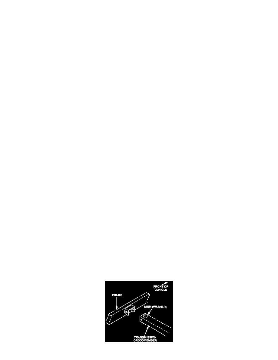
Check for the presence of a shim between the left side of the transmission crossmember and the frame rail bracket. If the shim is not present, raise
the vehicle on a hoist and support the transmission crossmember with an adjustable jack stand. Remove the bolt and lower the crossmember.
Install a suitable shim or washer to the top of the crossmember as shown below. The shim should be thick enough to ensure that no vertical
movement is possible between the crossmember and the frame bracket. The bolt should be tight in the hole when installed through the bracket and
crossmember. Tighten the bolt to 81 Nm ( 60 ft. lbs.).