
Viper GTS V10-488 8.0L (1998)
NOTE: If the vehicle is not within the required curb height specification range, do not perform a front or rear wheel alignment procedure at this
time. The vehicle MUST be within the required curb height specification to obtain an accurate wheel alignment.
Vehicle curb height on the Viper can be extremely affected if all rubber bushings used in the vehicles suspension are not tightened and torqued
with vehicle at specified design height. This is due to the extreme stiffness of the rubber bushings used in the vehicle's suspension components.
This will ensure all bushings are tightened and torqued to specifications, with the vehicle set to its specified design height. Then, recheck vehicle
curb height to verify it is within specification, before performing vehicle alignment procedure.
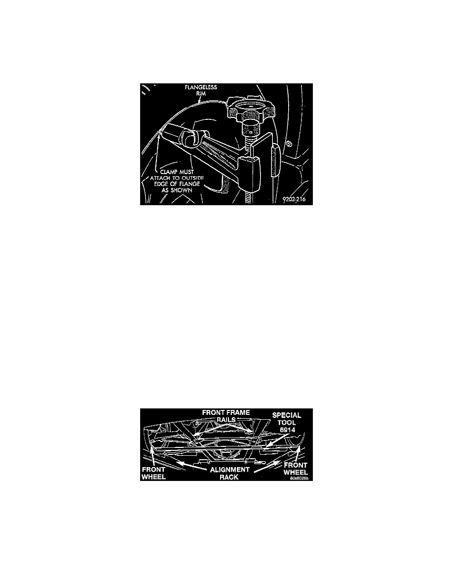
4. Attach alignment equipment heads onto the vehicle wheels. The Viper uses flangeless style wheels, thus any alignment equipment used must be
capable of attaching to outside edge of wheel rim lip.
5. Proceed with camber and caster angle adjustments.
Design Height Setting Procedure
1. Place the vehicle on a level flat surface that will allow access to the underside of the vehicle such as an alignment rack.
2. Check that all tires are at the preferred inflation pressure and adjust as necessary if they are not.
NOTE: When loosening the lower control arm mounting bolts be sure the alignment adjustment cams do not turn. The cams must stay in their
original position so the alignment of the vehicle is not affected.
3. Loosen the mounting bolts for the following suspension components. The mounting bolts must be loosened enough to allow the suspension of the
vehicle to move without loading (twisting) the rubber insert of the isolator bushings.
-
Front and rear lower control arm to frame bracket mounting bolts.
-
Front and rear upper control arm to frame bracket mounting bolts.
-
Front upper control arm to pivot bar mounting bolts.
-
Front and rear shock absorber to frame bracket mounting bolts.
-
Front and rear shock absorber to lower control arm mounting bolts.
NOTE: When the height checking fixtures are installed on the wheels, they must be positioned at the very bottom of the rim. This is required to
ensure the height checking fixtures are parallel to the bottom surface of the frame rails, which is required to achieve an accurate vehicle design
height measurement.
4. Position the Front Height Checking Fixture, Special Tool 6914, or equivalent on the inner flanges of the front rims.