
Viper GTS V10-488 8.0L (1998)
Power Steering Pump: Description and Operation
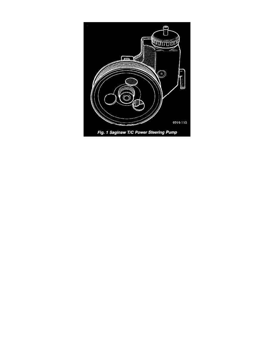
Hydraulic pressure for the operation of the power steering gear is provided by a belt driven power steering pump. The power steering pump used is a
constant flow rate and displacement, vane type pump. The Viper uses the Saginaw T/C style power steering pump, with the reservoir for the power
steering fluid attached directly to the power steering pump.
No repair procedures are to be done on the internal components of the Saginaw power steering pump.
The Saginaw T/C style power steering pump, consists of the power steering pump internal components and pump housing. This style power steering
pump however, has no reservoir internal to the pump for the power steering fluid. The reservoir for the power steering fluid is external and is mounted to
the housing of the power steering pump. The reservoir is retained to the pump housing using 2 steel clips.
The flow path of the high pressure power steering fluid is from the outlet of the power steering pump to the steering gear inlet port. The return flow path
of the low pressure power steering fluid is from the return port of power steering gear to the external fluid reservoir, where it is directly supplied back to
the power steering pump. A benefit of this type of fluid flow, is the power steering fluid tends to run at a lower temperature then an internal reservoir
type pump.
In the event of a power steering pump drive belt failure, manual steering control of the vehicle can still be maintained. However, under these conditions,
steering effort will significantly increase.
Because of unique shaft bearings, flow control levels and pump displacement, the power steering pump used on the Viper has been developed for this
specific vehicle application. If requiring replacement, be sure the power steering pump is replaced with a pump that is correct for this specific vehicle
application.
Rectangular pumping vanes carried by a shaft driven rotor move the fluid from the intake port to the cam ring pressure cavities. As the rotor begins to
turn, centrifugal force throws the vanes against the inside surface of the cam ring to pickup the residual oil. This oil is then forced into the high pressure
area. As more oil is picked up by the vanes the additional oil is forced into the cavities of the thrust plate through two crossover holes in the cam ring and
pressure plate. The crossover holes empty into the high pressure area between the pressure plate and the housing end cover.
When the high pressure area is filled, oil flows under the vanes in the rotor slots, forcing the vanes to follow the inside oval surface of the cam ring. As
the vanes reach the restricted area of the cam ring, oil is forced out from between the vanes. When excess oil flow is generated during high-speed
operation, a regulated amount of oil returns to the pump intake side through the flow control valve. The flow control valve reduces the power required to
drive the pump and holds down temperature build-up.