
Viper GTS V10-8.0L VIN E (1999)
Ball Joint Attachment To Lower Control Arm
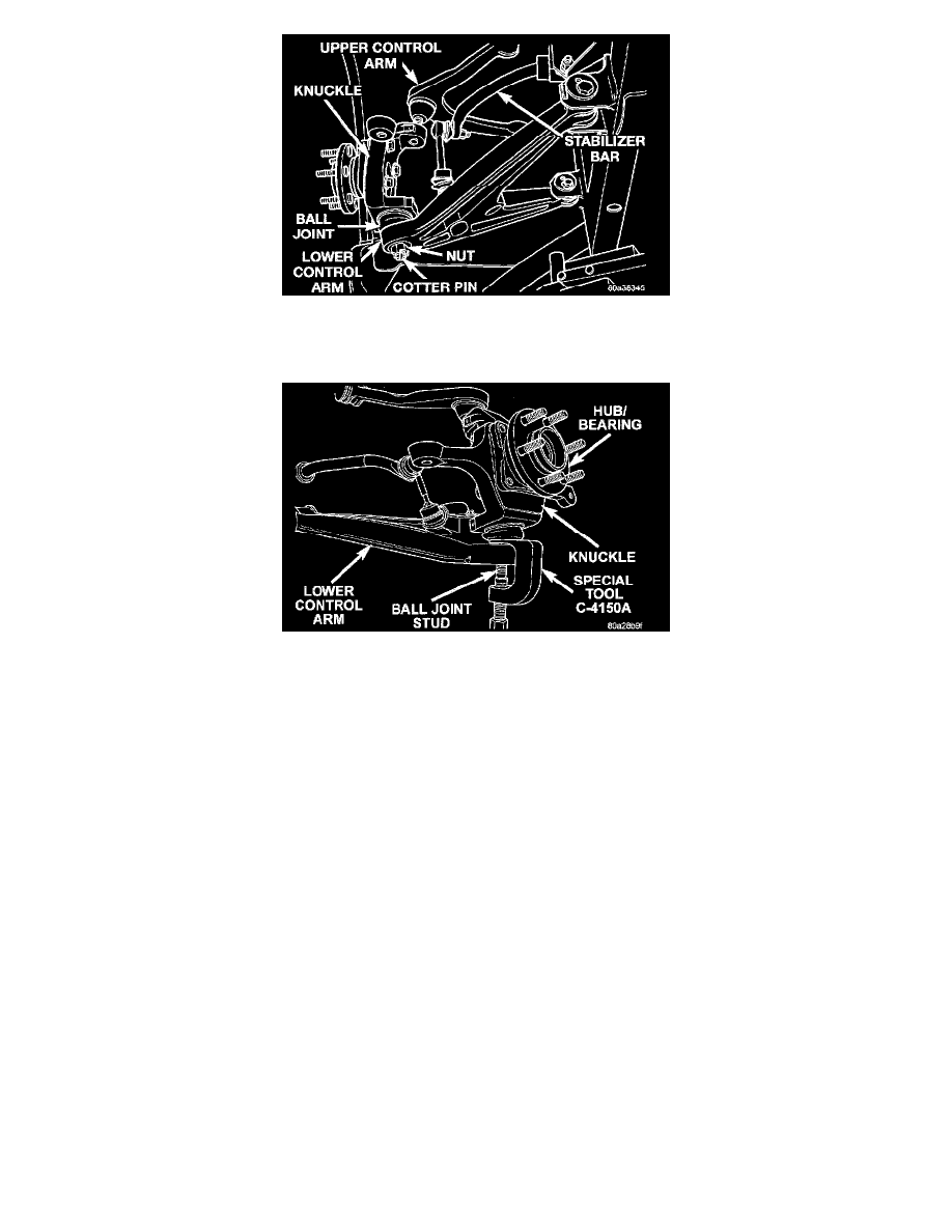
20. Remove the cotter pin and nut attaching the lower ball joint to the lower control arm.
Ball Joint Removal From Control Arm
21. Remove the stud of the lower ball joint from the lower control arm using Puller, Special Tool C-4150A.
22. Remove rear knuckle from the upper and lower control arms.
23. Transfer rear hub bearing to the replacement knuckle.
INSTALLATION
1. Install the knuckle on the upper and lower ball joints. Install castle nuts on upper and lower ball joints.
2. Install the toe link tie rod end on the knuckle. Install the castle nut on the stud of the tie rod end. Tighten the castle nut to a torque of 34 Nm (25 ft.
lbs.). Install cotter pin in stud of tie rod end.
3. Tighten the lower ball joint castle nut to a torque of 160 Nm (118 ft. lbs.). Install cotter pin in lower ball joint.
4. Tighten the upper ball joint castle nut to a torque of 102 Nm (75 ft. lbs.). Install cotter pin in upper ball joint.
5. Install the driveshaft yoke from the back side of the rear hub/bearing assembly.
6. Install the driveshaft.
7. Install the shock absorber.
8. Install the tie strap attaching the park brake cable to the rear knuckle.
9. Install the brake rotor on the rear hub/bearing.
10. Install the brake caliper on the knuckle.
11. Lubricate the caliper slide pins and bushings with silicone lubricant.
12. Install the brake caliper to knuckle lower slide pin bolt. Finger tighten the lower slide pin bolt. Do not torque at this time.
13. Install the brake caliper to knuckle upper slide pin bolt. Tighten the upper slide pin bolt to a torque of 32 Nm (24 ft. lbs.).
14. Now, tighten the lower slide pin bolt to a torque of 51 Nm (38 ft. lbs.).
15. Install the wheel and tire assembly. Tighten the wheel mounting nuts in the proper sequence until all nuts are torqued to half specification. Then
repeat the tightening sequence to the full specified torque of 122 Nm (90 ft. lbs.).
16. Lower vehicle to ground from jack stands or hoist.
17. Position vehicle on an alignment rack.
18. Set the vehicle to design height.
19. Once the vehicle is at design height, tighten the shock absorber upper and lower mounting bolts to a torque of 176 Nm (130 ft. lbs.).
20. Remove the ballast (weight) from the vehicle. Correctly jounce the vehicle letting it return to its curb height.
21. Correctly measure the vehicles curb height.
22. Check and adjust the vehicle's rear static wheel toe position.