
Viper GTS V10-8.0L VIN E (1999)
Clutch Pedal Assembly: Service and Repair
Installation
CAUTION:
-
When installing adjustable pedal assembly in vehicle, care must be taken so as not to kink the actuator cables. If cables are kinked binding will
occur when adjusting pedals.
-
Prior to installing the adjustable pedal assembly in the vehicle, verify that tape sealant is installed on the pedal assembly in the following locations.
The back surface of the throttle pedal stop plate and the clutch/brake pedal bracket to side of toe box mounting location. This sealant tape must be
installed to ensure an air and water tight seal is provided to the passenger compartment of the vehicle.
1. Install the adjustable clutch, brake, accelerator pedal as an unit into the vehicle.
2. Install the clutch/brake pedal mounting bracket on the studs of the vacuum booster.
3. Align holes in top of clutch/brake pedal mounting bracket with holes in dash panel. Loosely install the 2 bolts mounting the pedal bracket to dash
panel. Do not tighten bolts.
4. Loosely install the 4 nuts mounting the clutch/brake pedal bracket to the vacuum booster studs.
5. Install the bolt mounting the side of the clutch/brake pedal mounting bracket to the toe box area of the dash panel.
6. Tighten the clutch/brake pedal mounting bracket attaching bolts and nuts in the following sequence and torques listed below.
-
Tighten clutch/brake pedal mounting bracket to vacuum booster nuts to a torque of 29 Nm (250 inch lbs.).
-
Tighten clutch/brake pedal mounting bracket to dash panel upper mounting bolts to a torque of 20 Nm (180 inch lbs.).
-
Tighten clutch/brake pedal mounting bracket to side dash panel mounting bolt to a torque of 4 Nm (35 inch lbs.).
7. Install the powertrain control module on the dash panel. Be sure ground wire is installed on the front mounting screw of the powertrain control
module.
8. Install the shield covering the powertrain control module.
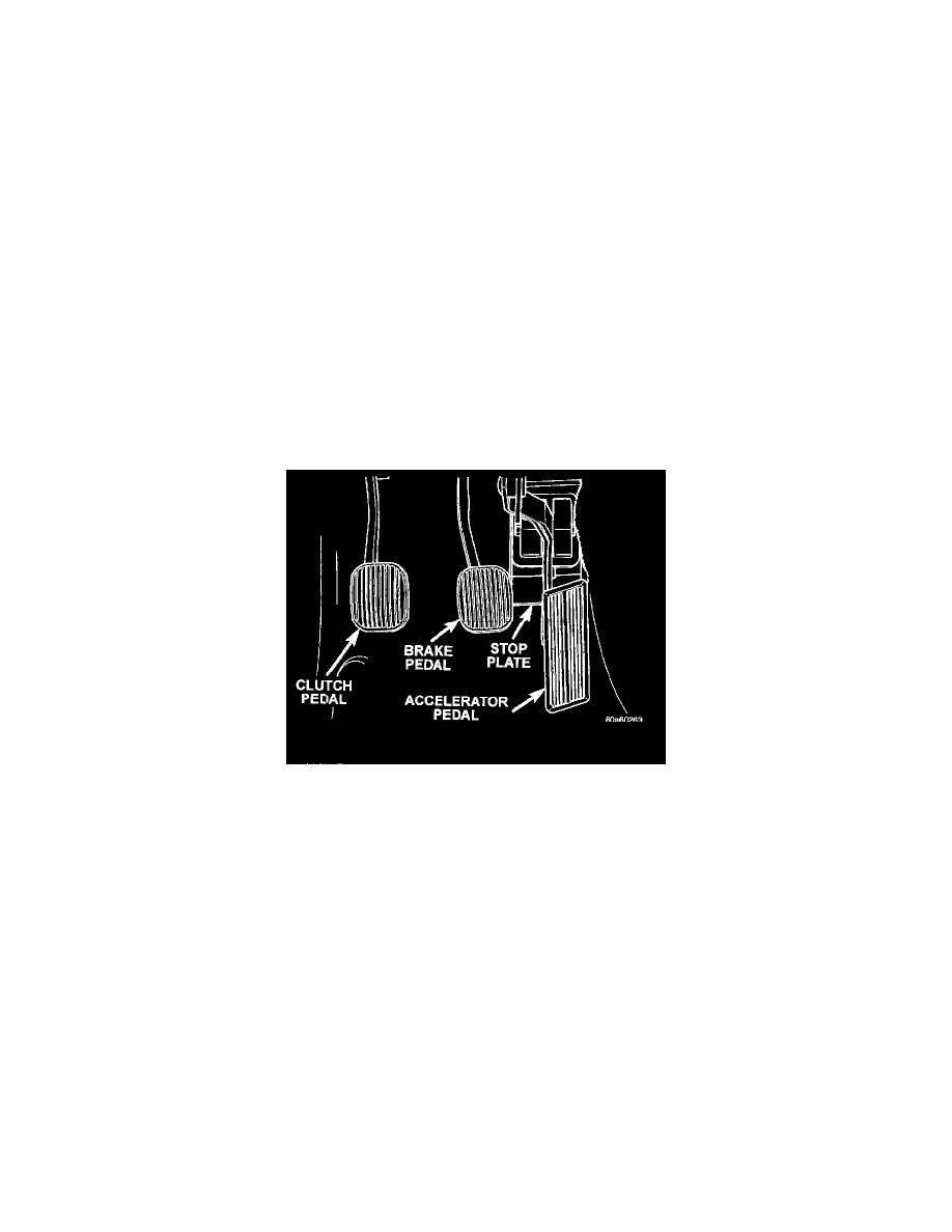
Accelerator Pedal Stop Plate
CAUTION: Be sure sealant is installed on back surface of stop plate.
9. Install the accelerator pedal on dash panel. When installing accelerator pedal be sure stop plate is installed under the accelerator pedal.
10. Install accelerator pedal mounting nuts on engine side of dash panel. Tighten both mounting nuts to a torque of 12 Nm (105 inch lbs.).
11. Using Mopar Lubriplate or an equivalent, lightly lubricate the surface of the brake pedal striker which the plunger of the stop lamp switch
contacts.
NOTE: Prior to installing stop lamp switch into bracket, the plunger must be moved to its fully extended position using the procedure in Step 12.
12. Hold stop lamp switch firmly in one hand. Using other hand, pull outward on the plunger of the stop lamp switch until it has ratcheted out to its
fully extended position.
13. Install the stop lamp switch on the clutch/ brake pedal mounting bracket. Clip the stop lamp switch wiring harness to the clutch/brake pedal
mounting bracket.
14. Install the clutch master cylinder into the dash panel. The clutch master cylinder is installed by pushing it firmly into the dash panel and then
rotating it clockwise until it engages and locks into the clutch/ brake pedal bracket on the inside of the vehicle.
15. Install the hydraulic clutch master cylinder actuation rod on the pin of the clutch pedal. Actuation rod is installed by carefully forcing the actuation
rod and retaining clip onto the pin on the clutch pedal.
16. Install the vacuum booster push rod on the brake pedal pin.
CAUTION: When installing the retaining clip on the brake pedal pin a NEW retaining clip must be used to ensure the retention of the vacuum
booster push rod.