
Viper RT-10 V10-8.0L VIN E (1997)
Engine Control Module: Description and Operation
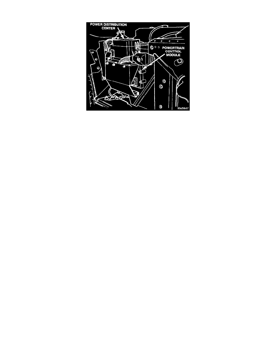
Fig 1 Powertrain Control Module
POWERTRAIN CONTROL MODULE (PCM)
The PCM regulates the ignition system (Fig. 1). The PCM supplies battery voltage to the ignition coil through the Automatic Shutdown (ASD)
Relay. The PCM also controls the ground circuit for the ignition coils. By switching the ground path for the coil ON and OFF, the PCM adjusts
ignition timing to meet changing engine operating conditions.
During the crank-start period the PCM advances ignition timing a set amount. During engine operation the following inputs determine the amount
of spark advance provided by the PCM.
-
Intake air temperature
-
Coolant temperature
-
Engine RPM
-
Available manifold vacuum
-
Throttle position sensor
The PCM also regulates the fuel injection system.
Sensor Return-PCM Input
The sensor return circuit provides a low electrical noise ground reference for all of the systems sensors. The sensor return circuit connects to
internal ground circuits within the powertrain control module.
CIRCUIT OPERATION
Battery Feed
Circuit A14 is used to provide a constant battery feed to the Powertrain Control Module (PCM). This circuit connects from the PCM to the Power
Distribution Center (PDC). The A14 circuit is protected by a 20 amp fuse located in cavity 15 of the PDC.
Circuit A14 is spliced internal to the PDC and supplies battery voltage to the contact side of the Automatic Shut Down (ASD) relay.
Circuit F13 supplies a constant battery feed to the wiper control module. The F13 circuit is protected by a 20 amp fuse located in cavity 19 of the
fuse block and HOT at all times.
Ignition Feed
Circuit V6 supplies a ignition feed input to the wiper control module. The V6 circuit is protected by a 15 amp fuse located in cavity 3 of the fuse
block. This fuse is HOT in the RUN and ACCESSORY position.
Power (Device) Ground
Circuit Z12 connects to cavities A31 and A32 of the Powertrain Control Module (PCM) connector. The Z12 circuits provides ground for the PCM
internal drivers that operate high current devices like fuel injectors and ignition coils.
Internal to the PCM, the power (device) ground circuit connects to the PCM sensor return circuit from circuit K4.