
Viper RT-10 V10-8.0L VIN E (1997)
2-1/2 inches +/- 1/4 inch
(64 mm +/- 6 mm).
d.
If the vehicle does not meet curb height specifications, continue with Section "0 - Setting the Vehicle Design Height" before continuing with
this procedure. If the curb height is within specifications, continue with Step 4 of this procedure.
NOTE:
Vehicle curb height can be affected if the rubber bushings used in the vehicle's suspension are not tightened with the vehicle at Design
Height. This is due to the extreme stiffness of the rubber used in the suspension component bushings.
4.
Install the wheel alignment equipment onto the vehicle per alignment equipment manufacturer's instructions.
NOTE:
The vehicle is equipped with flangeless style wheels, thus any alignment equipment used must be capable of attaching to the outside edge of
the wheel rim lip.
CAUTION:
Both front and rear caster angle on the vehicle must be read directly off the front and rear knuckle through the use of inclinometer sensors
attached to the DRB III scan tool. Do not use the alignment machine's sweep method to measure caster angle.
NOTE:
All necessary adapters, cables, switch box and inclinometers are available in Viper Essential Tool Kit # 6990.
5.
Use the following procedure to connect and calibrate the DRB III and inclinometers.
NOTE:
The DRB III must have a Super Card 2 installed to perform caster measurements.
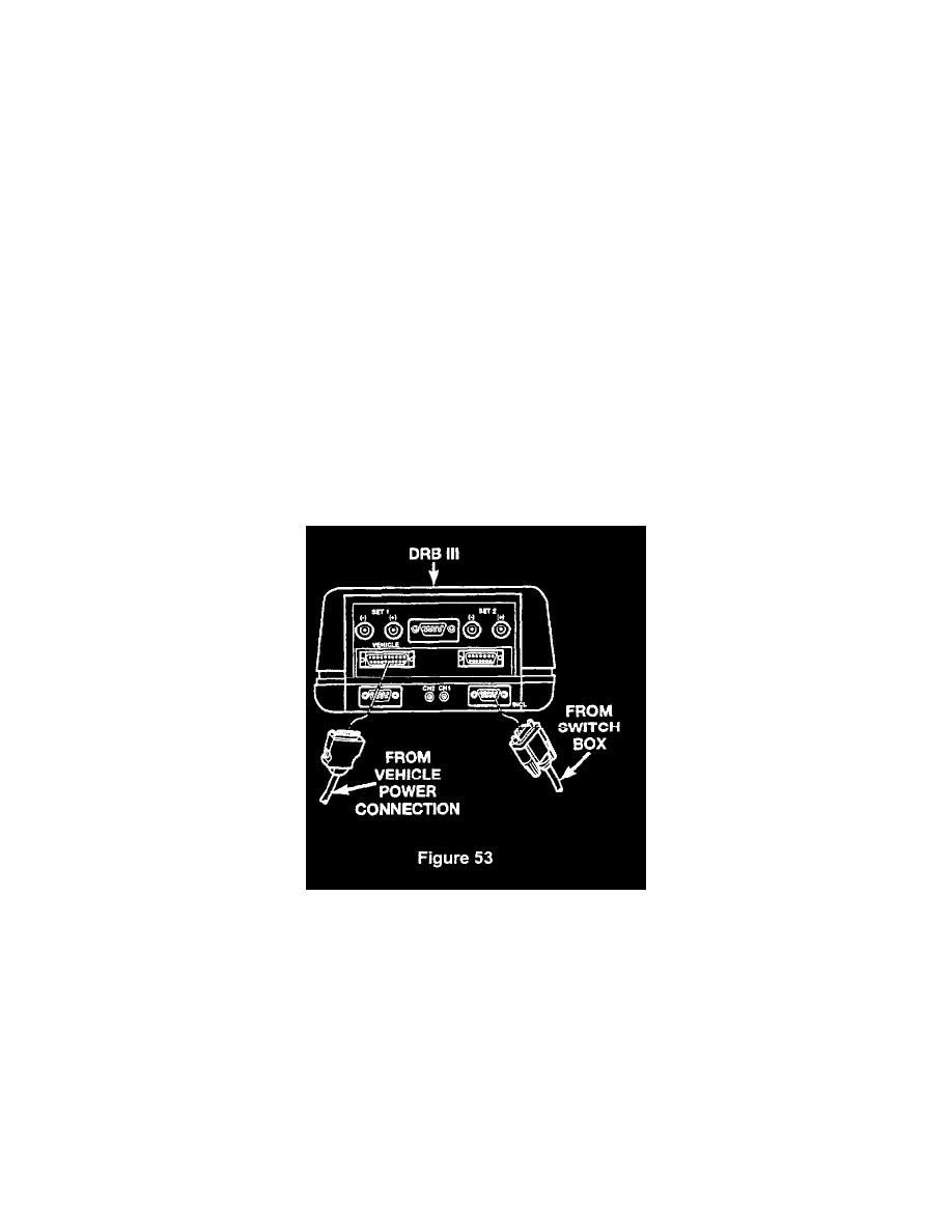
a.
Plug the cable from the switch box (Special Tool # 6996) into the PEP module connector on the DRB III marked "INCL" (Figure 53).
b.
Plug the power cable (supplied with the DRB III kit) into the DRB III power connector marked "VEHICLE" (Figure 53).