
Viper SRT-10 V10-8.4L (2008)
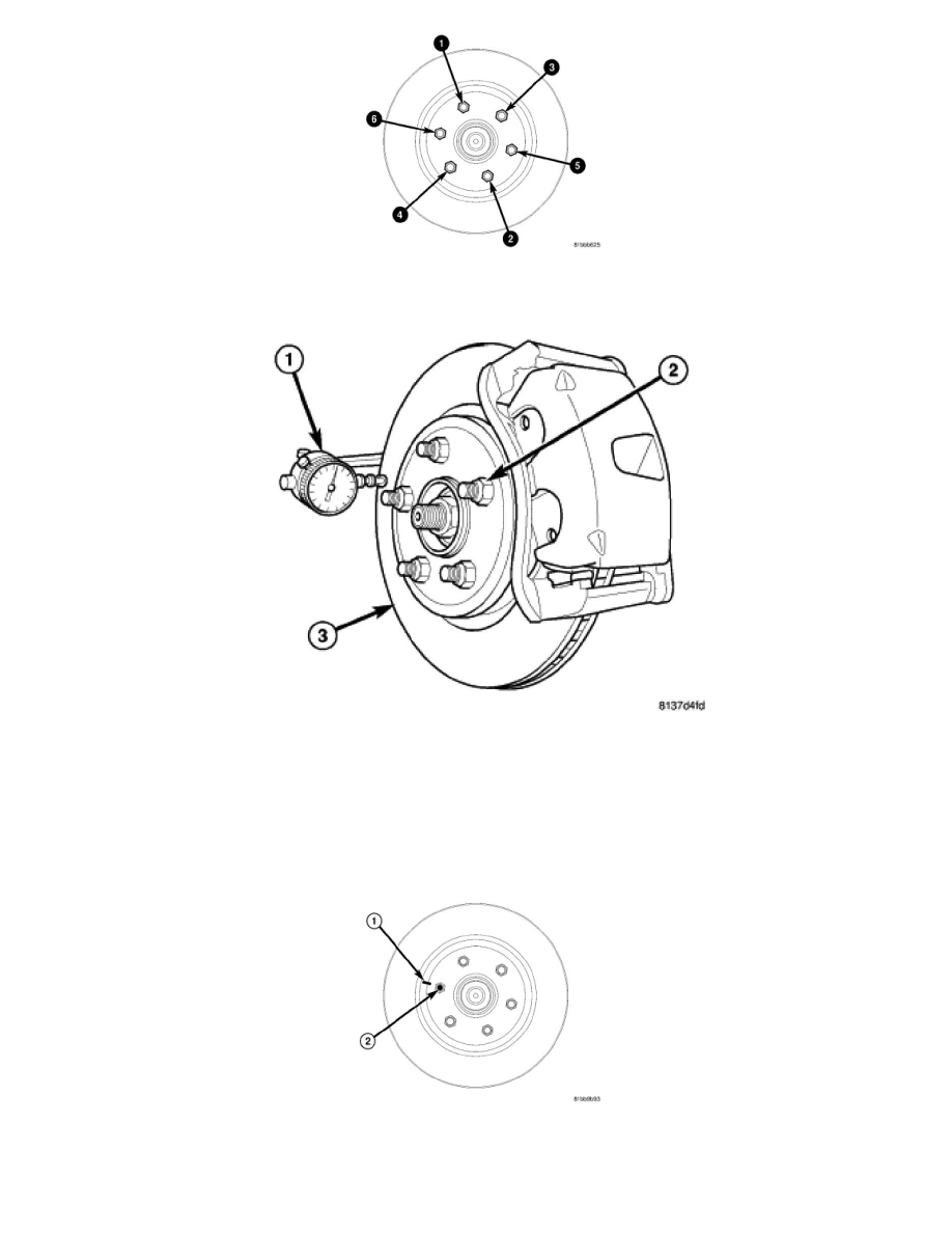
3. Install standard wheel mounting nuts, flat side to rotor, on all the wheel studs. Progressively tighten the nuts using the pattern shown to 135 Nm
(100 ft. lbs.).
NOTE: Dial Indicator, Special Tool 9524, can be used in conjunction with C-3339A to measure in millimeters instead of inches. Dial indicator
9524 includes a finer scale to measure lower, tighter tolerances.
4. Mount Dial Indicator (1), Special Tool C-3339A, with Wheel, Special Tool 25w, or equivalent, to the knuckle. Position the dial indicator wheel to
contact the rotor braking surface approximately 10 millimeters from the outer edge of the rotor (3).
5. Slowly rotate the brake rotor checking lateral runout, marking the low and high spots. Record these measurements.
6. Check and record the runout on the opposite side of the rotor in the same fashion, marking the low and high spots.
7. Compare runout measurement to specifications.See: Specifications
If runout is in excess of specifications, check the lateral runout of the hub face. Before removing the rotor from the hub, place a chalk mark across both
the rotor (1) and the one wheel stud (2) closest to where the high runout measurement was taken. This way, the original mounting spot of the rotor on the
hub is indexed.