
Viper SRT-10 V10-8.4L (2008)
8. Remove the rotor from the hub. See: Service and Repair/Removal and Replacement/Brake Rotor - Removal
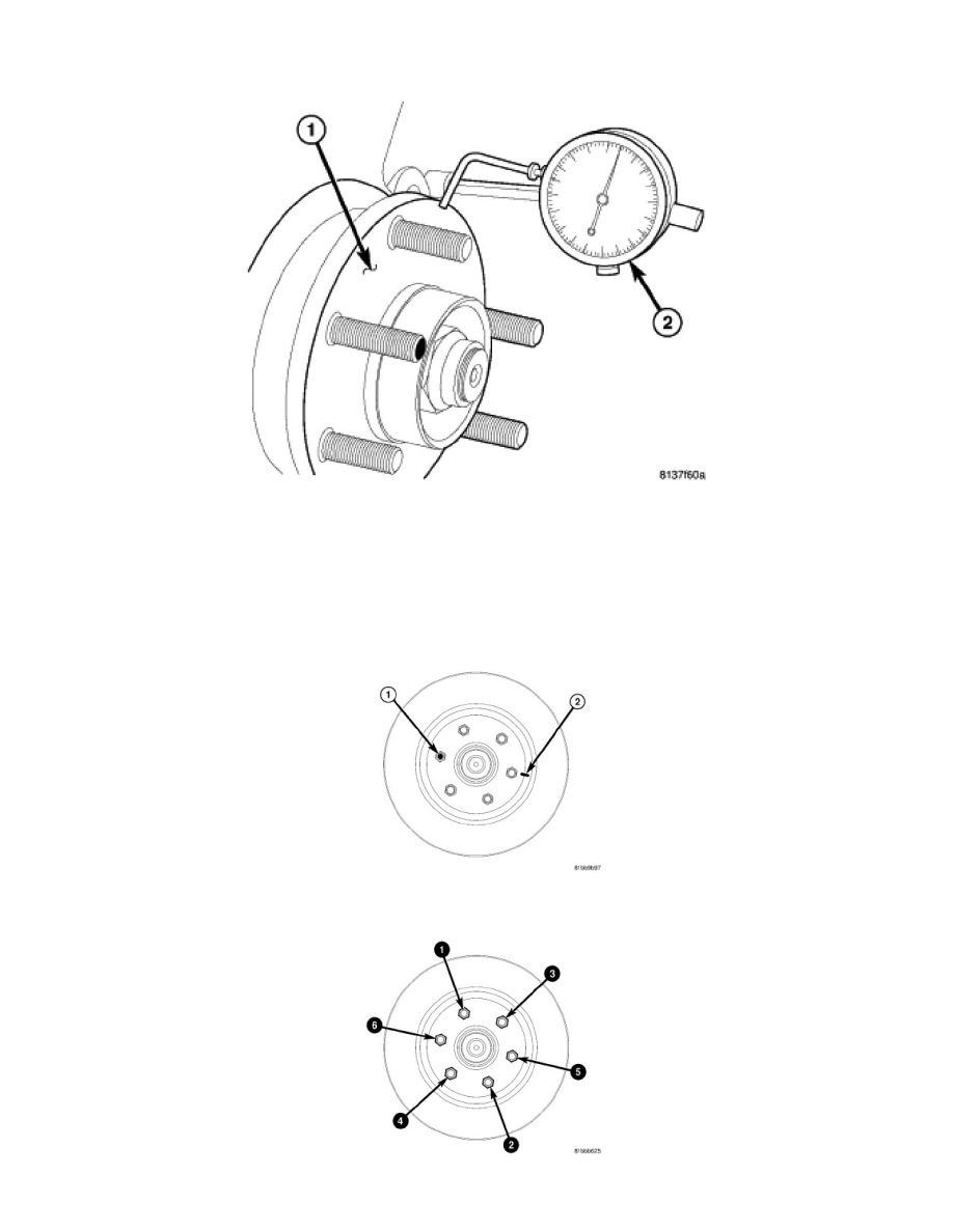
NOTE: Before measuring hub runout, clean the hub face surface with an appropriate cleaner. This provides a clean surface to get an accurate
indicator reading.
9. Mount Dial Indicator (2), Special Tool C-3339A, to the knuckle. Position the dial indicator stem so it contacts the hub face (1) near the outer
diameter. Care must be taken to position the stem outside of the stud circle, but inside of the chamfer on the hub rim.
10. Slowly rotate the hub measuring runout. Hub runout should not exceed 0.08 mm (0.003 inch). If runout exceeds this specification, the hub must be
replaced. See: Steering and Suspension/Steering/Front Steering Knuckle/Service and Repair/Front Steering Knuckle - Removal See:
Maintenance/Wheels and Tires/Wheel Bearing/Service and Repair/Rear Hub / Bearing - Removal
11. If hub runout does not exceed this specification, install the original rotor back on the hub, aligning the chalk mark on the rotor (2) with the wheel
mounting stud that is directly across (or 180°) from the original stud (1).
12. Install standard wheel mounting nuts, flat side to rotor, on all the wheel studs. Progressively tighten the nuts using the pattern shown to 135 Nm