
Viper SRT-10 V10-8.4L (2008)
Alignment: Service and Repair
Wheel Alignment
WHEEL ALIGNMENT
NOTE: Wheel alignment must be checked and adjusted to the preferred specifications with the vehicle at Design Height rather than at Curb
Height.
1. Place vehicle on wheel alignment rack or drive-on lift per equipment manufacturer's recommendations.
2. Perform pre-wheel alignment inspection. See:
3. Set vehicle to specified design height. See:
4. Remove Suspension Height Gages, Special Tools 6914 and 8897, from vehicle.
5. Attach wheel alignment equipment following equipment manufacturer's instructions.
NOTE: Align the vehicle starting with the rear suspension, then proceed to the front suspension. Always set toe last.
6. Proceed with Camber And Caster Angle.
CAMBER AND CASTER ANGLE
Camber and caster angles on this vehicle are adjustable using cams located on the lower control arm bushing pivot bolts. Both front and rear camber and
caster are adjustable on this vehicle. Camber readings are viewed on the wheel alignment equipment, but caster readings are viewed on the scan tool as
described in INCLINOMETER SETUP FOR CASTER ANGLE VIEWING.
CAUTION: Prior to any cam bolt rotation, cam bolt lock nuts must be loosened, allowing lower control arm mounting brackets to spread, thus
allowing free movement of control arm bushings. If not performed, serious bracket bending, weld breakage of cam retainer, free cam and cam
bolt shank fracturing, or thread damage can occur. It may be necessary to tap bracket ears away from bushings to allow unrestricted cam bolt
movement.
CAMBER ANGLE
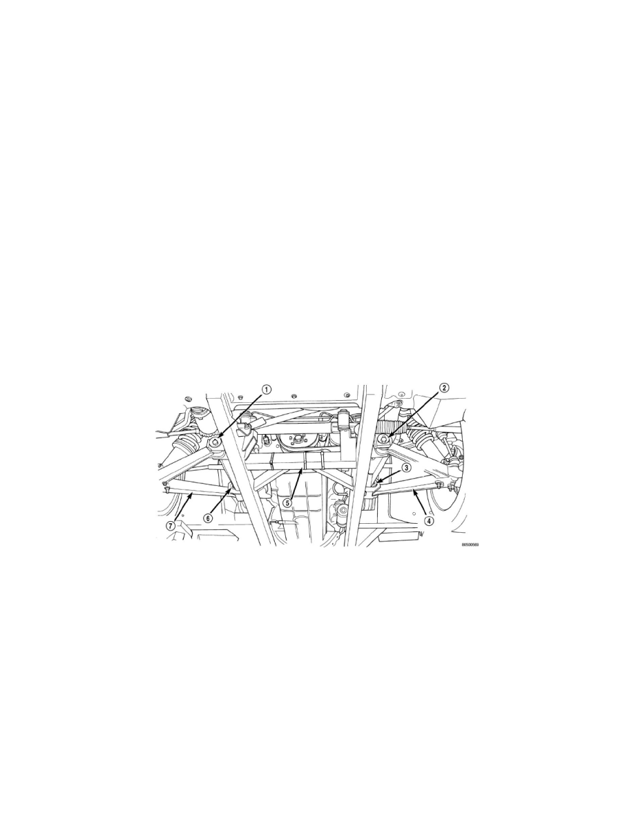
Camber angle adjustment involves the repositioning of the lower control arm (4, 7) pivot bolts using the adjustment cams. There are two cams located on
each lower control arm pivot bolt (1, 2), four per each corner of the vehicle front and rear. Repositioning of the pivot bolt cams in the same direction
moves the lower ball joint in or out to obtain the required camber specifications.
CASTER ANGLE
Caster angle adjustment, like camber angle adjustment, involves the repositioning of the lower control arm (4, 7) pivot bolts using the adjustment cams.
There are two cams located on each lower control arm pivot bolt (1, 2), four per each corner of the vehicle front and rear. Repositioning of the pivot bolt
cams in opposite directions moves the lower ball joint fore or aft as required to obtain the required caster specifications.
INCLINOMETER SETUP FOR CASTER ANGLE VIEWING