
Viper SRT-10 V10-8.4L (2008)
LOCATIONS
Section 8W-91 contains connector/ground/splice location illustrations. The illustrations contain the connector name (or number)/ground number/splice
number and component identification. Connector/ground/splice location charts in section 8W-91 reference the figure numbers of the illustrations.
The abbreviation T/O is used in the component location section to indicate a point in which the wiring harness branches out to a component. The
abbreviation N/S means Not Shown in the illustrations
Section Identification and Information
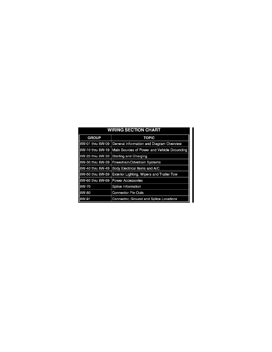
DESCRIPTION - SECTION IDENTIFICATION AND INFORMATION
The wiring diagrams are grouped into individual sections. If a component is most likely found in a particular group, it will be shown complete (all wires,
connectors, and pins) within that group. For example, the Auto Shutdown Relay is most likely to be found in Group 30, so it is shown there complete. It
can, however, be shown partially in another group if it contains some associated wiring.
Splice diagrams 8W-70 show the entire splice and provide references to other sections the splices serves. Section 8W-70 only contains splice diagrams
that are not shown in their entirety somewhere else in the wiring diagrams.
Section 8W-80 shows each connector and the circuits involved with that connector. The connectors are identified using the name/number on the diagram
pages.
Removal
REMOVAL
1. Disconnect battery.
2. Release Connector Lock.
3. Disconnect the connector being repaired from its mating half/component.
4. Remove the dress cover (if applicable).