
Viper SRT-10 V10-8.4L (2008)
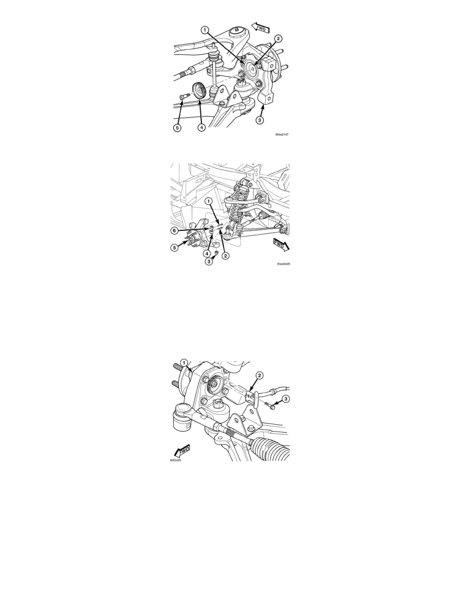
5. Install ABS wheel speed sensor tone wheel (4). Tighten mounting bolt (4) to 17 Nm (13 ft. lbs.).
6. Install steering knuckle (5) on lower ball joint stud. Loosely install castle nut (4) on stud.
7. Install steering knuckle (5) on upper ball joint stud. Loosely install castle nut (6) on stud.
8. Install outer tie rod onto steering knuckle. Install a NEW tie rod nut (3). Tighten nut to 75 Nm (55 ft. lbs.).
9. Tighten upper ball joint castle nut (6) to 102 Nm (75 ft. lbs.). Once nut is tightened to specified torque, it may be necessary to continue
tightening nut to allow installation of cotter pin through nut castle and hole in ball joint stud (DO NOT LOOSEN NUT).
10. Install cotter pin (1) through upper ball joint castle nut and stud.
11. Tighten lower ball joint castle nut (4) to 160 Nm (118 ft. lbs.). Once nut is tightened to specified torque, it may be necessary to continue
tightening nut to allow installation of cotter pin through nut castle and hole in ball joint stud (DO NOT LOOSEN NUT).
12. Install cotter pin (2) through lower ball joint castle nut and stud.
13. Install ABS wheel speed sensor head (2) in steering knuckle (1). Install and tighten mounting bolt (3) to 11 Nm (100 in. lbs.).
14. Install brake rotor and brake caliper on knuckle. See: Brakes and Traction Control/Disc Brake System/Brake Rotor/Disc/Service and
Repair/Removal and Replacement/Brake Rotor - Installation
15. Install wheel and tire assembly See: Wheels and Tires/Service and Repair/Removal and Replacement/Tires and Wheels - Installation.
Progressively tighten wheel mounting nuts in proper sequence to 135 Nm (100 ft. lbs.).
16. Lower vehicle.
17. Position vehicle on alignment rack/drive-on hoist.
18. Perform wheel alignment See: Alignment/Service and Repair.
19. Road test vehicle to ensure proper operation.