
W150 1/2 Ton Pickup 4WD V8-318 5.2L VIN Y FI (1988)
Toe-in is measured in inches and is the distance the leading edges of the tires are closer than the trailing edges. Toe-in is considered the
most serious cause for excessive tire wear. Toe-in is the last of the alignment angles to be set in the front wheel alignment operation.
Steering Axis Inclination is measured in degrees and is the amount the spindle support center line is tilted from true vertical. It has a fixed
relationship with camber settings and does not change except when a spindle or ball joint is damaged or bent. This angle is not adjustable
and damaged parts must be replaced.
Toe-Out on Turns (Turning Radius) is measured in degrees and is the amount one front wheel turns sharper than the other on a turn. This
angle is designed into the steering arm in relationship to the wheelbase of the vehicle and is not adjustable. When checking the turning
radius and it is found not to be within the recommended specifications, look for possible bent or damaged components.
Pre-Alignment Inspection
Before any attempt is made to change or correct the wheel alignment factors the following inspection and necessary corrections must be made on those
parts which influence the steering of the vehicle.
1. Check and inflate tires to recommended pressure. All tires should be the same size and be in good condition and have approximately same wear.
Make a note of the type of tire tread wear which will aid in diagnosing.
2. Check and adjust front wheel bearings.
3. Check front wheel and tire assembly for radial and lateral runout (follow the Equipment Manufacturers Instruction).
4. Check wheel and tire for unbalance conditions both static and dynamic which could affect steering.
5. Inspect ball joints and all steering linkage pivot points for excessive looseness.
6. Check shock absorbers for leaks and jounce vehicle to determine if shock absorbers have proper control.
7. Check steering gear for roughness, binding or sticking condition and adjust as necessary.
8. Check rear springs for cracks or broken leaves and U-bolts for proper tightness and measure height differential between left and right sides of
vehicle. (Vehicle should be on level floor or on alignment rack) with a full tank of fuel and no luggage or passenger load.
Note: To obtain accurate readings, vehicle should be jounced in following manner just prior to taking each measurement (Caster-Camber and Toe):
Grasp bumpers at center (rear bumper first) and jounce up and down several times. Always release bumpers on the down cycle after jouncing both rear
and front ends an equal number of times.
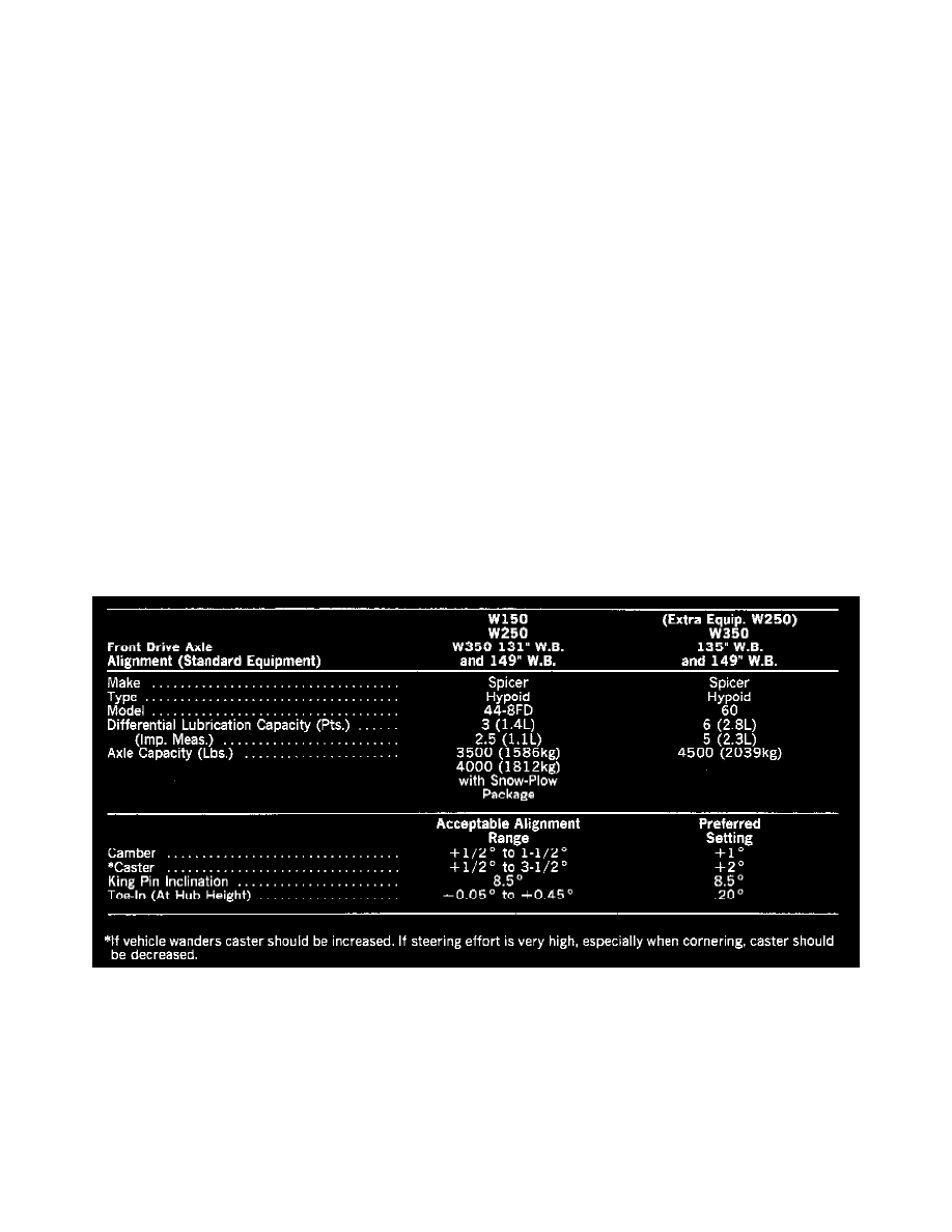
Specifications
Front wheel alignment settings must be held to specifications to hold tire wear to a minimum and to maintain steering ease and handling of vehicle.
The equipment manufacturers recommended procedure should always be followed. Any parts of the front suspension system should be replaced if they
are found to be bent.
CAUTION: DO NOT ATTEMPT TO STRAIGHTEN ANY BENT PART.
1. Prepare vehicle for measuring wheel alignment.
2. Remove all foreign material from exposed threads of cam adjusting bolts.