
W350 1 Ton Pickup 4WD V8-360 5.9L VIN 1 4-bbl (1988)
Speed Control Servo: Testing and Inspection
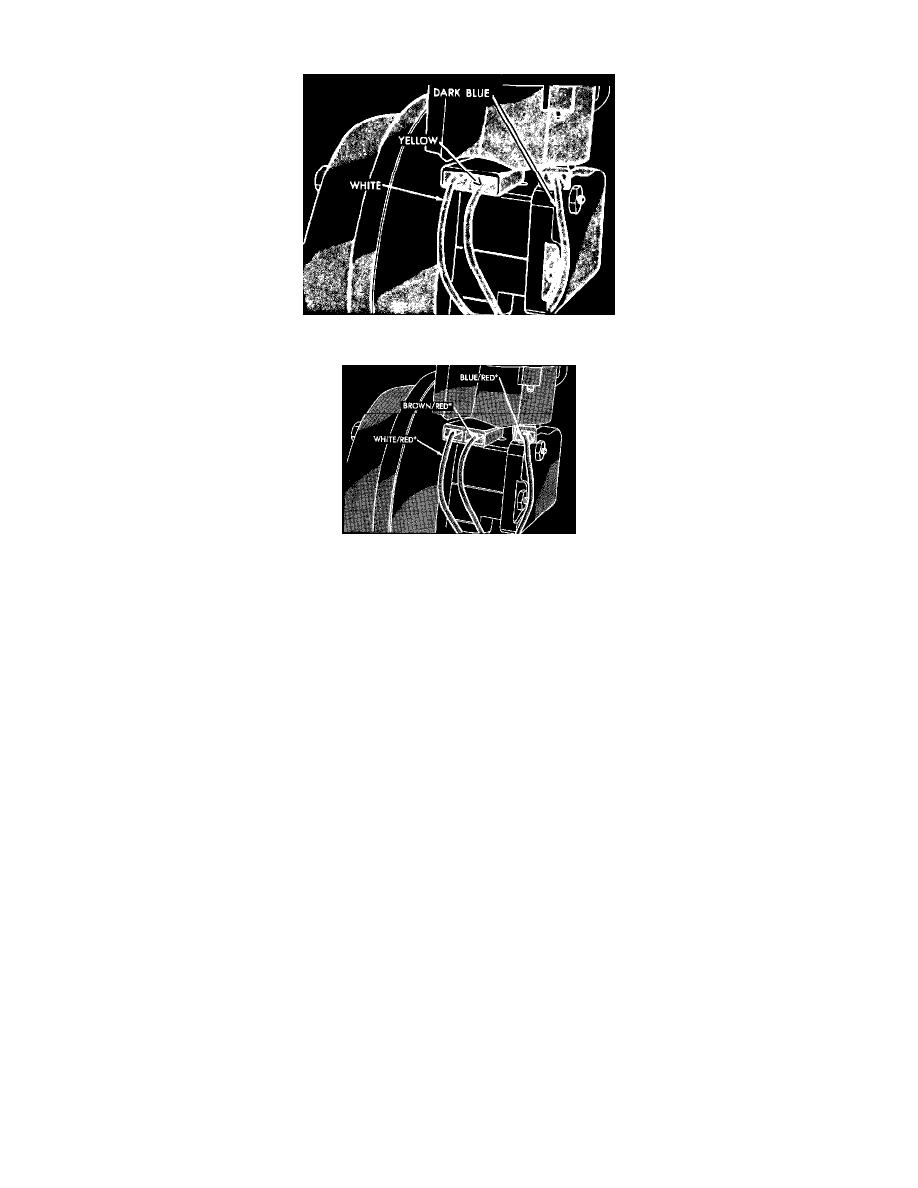
Fig. 14 Servo terminals, front wheel drive models
Fig. 83 Servo Terminal Electrical Connections
1. Connect a test lamp between brown/red wire and ground then proceed as follows:
a. Place speed control switch and ignition switch in the On position. Test lamp should illuminate.
b. Depress Set button. Test lamp should go out and a clicking noise should be heard at servo.
c. Release Set button. Test lamp should illuminate and a clicking noise should be heard at servo.
d. If test results are not satisfactory, possible causes may be a blown fuse, faulty wiring, or a defective speed control switch or servo.
2. Connect a test lamp between white/red wire and ground then proceed as follows:
a. Place speed control switch and ignition switch in On position. Test lamp should be off.
b. Depress Set button. Test lamp should illuminate.
c. If test results are not satisfactory, possible causes may be faulty wiring, or a defective speed control switch.
3. Connect a test lamp between blue/red wire and ground then proceed as follows:
a. Place speed control switch and ignition switch in On position. Test lamp should illuminate.
b. If test result is not satisfactory, possible causes may be faulty wiring, or defective brake, clutch, or speed control switches.