
W350 1 Ton Pickup 4WD V8-360 5.9L VIN 1 4-bbl (1988)
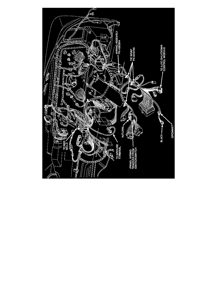
FIGURE 2-C - INSTRUMENT PANEL WIRING
9.
Route the wiring assembly, PN 4362804, along the existing instrument panel ignition switch wiring from the bulkhead connector, and
behind the fuse block to the existing red mold connector and instrument panel ground terminal as shown in Figure 2-C.
10.
Secure the wiring assembly, PN 4362804, using two tie wraps, PN 6015756, as shown in Figure 2-C.
11.
Install the eyelet terminal (black wire) from the wiring assembly, PN 4362804, onto the instrument panel ground stud located to the right of
the steering column as shown in Figure 2-C.
12.
Insert the single bullet terminal (red mold) from the wiring assembly, PN 4362804, into the existing 3-way red molded connector, from the
main instrument panel wiring harness located near the radio as shown in Figure 2-C.