
W350 1 Ton Pickup 4WD V8-360 5.9L VIN 1 4-bbl (1988)
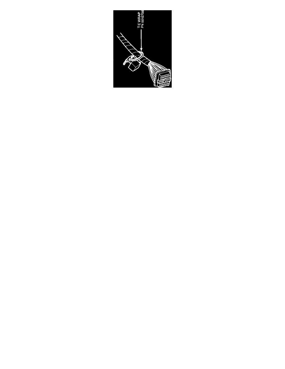
FIGURE 2-E - TYPICAL CONTROL MODULE MOUNTING
13.
Connect the control (auto shut-down) module, PN 5226640, to the supplied natural colored 8-way connector from the wiring assembly, PN
4362804. Secure the module onto the main instrument panel wiring harness with a tie wrap, PN 6015756, close to the bulkhead connector
as shown in Figure 2-E.
B.In-Tank Fuel Pump Installation
1.
Remove the fuel tank gauge unit from the fuel tank per the service manual procedure and discard. Install the new seal (or gasket) and
gauge/pump unit from the applicable kit. USE EXTREME CAUTION TO PROTECT THE FLOAT AND GAUGE ASSEMBLY
DURING INSTALLATION INTO THE FUEL TANK.
2.
Remove the supply and return hose assemblies at the chassis tubes. Retain the convolute sleeve and discard the hoses.
a.
All Models Except Ramcharger
Obtain a 5/16" diameter by 10-3/4" long fuel supply hose and a 1/4" diameter by 11-1/2" long fuel return hose from the 25 foot
spools (standard grade), PN 4443176 (.31" diameter), and 4443175 (.25" diameter). These parts are not included in the kit.
b.
Ramcharger Only
Obtain a 5/16" diameter by 31" long fuel supply hose and a 1/4" diameter by 28" long fuel return hose from the 25 foot spools
(standard grade), PN 4443176 (.31" diameter), and 4443175 (.25" diameter). These parts are not included in the kit.
3.
Install the convolute sleeves removed in Step B.2. onto the newly obtained hoses, and attach these assemblies to the respective chassis
tubes, using the clamps provided.
4.
With the fuel tank partially raised, connect the fuel return hose assembly and the fuel supply hose assembly, using the hose clamps
provided.