
W350 1 Ton Pickup 4WD V8-360 5.9L VIN 1 4-bbl (1988)
April 9, 1990
No.
21-13-90
(C21-33-9)
P-1040
BODY CODE LEGEND
B/AB - RAM VAN/WAGON (RWD) D/AD - RAM PICKUP/RAM CAB & CHASSIS/RAMCHARGER (RWD,4WD) POWER RAM CAB &
CHASSIS (4WD) N/AN - DAKOTA/DAKOTA SPORT/DAKOTA CONVERTIBLE DAKOTA CAB & CHASSIS
THIS BULLETIN SUPERSEDES TECHNICAL SERVICE BULLETIN 21-26-89 WHICH SHOULD BE REMOVED FROM YOUR FILES. AN
ADDITIONAL VALVE BODY SEPARATOR PLATE HAS BEEN LISTED UNDER "PARTS REQUIRED".
SYMPTOM/CONDITION
Customer complaint of harsh transmission engagement when shifting from PARK or NEUTRAL to DRIVE with the engine at normal curb idle.
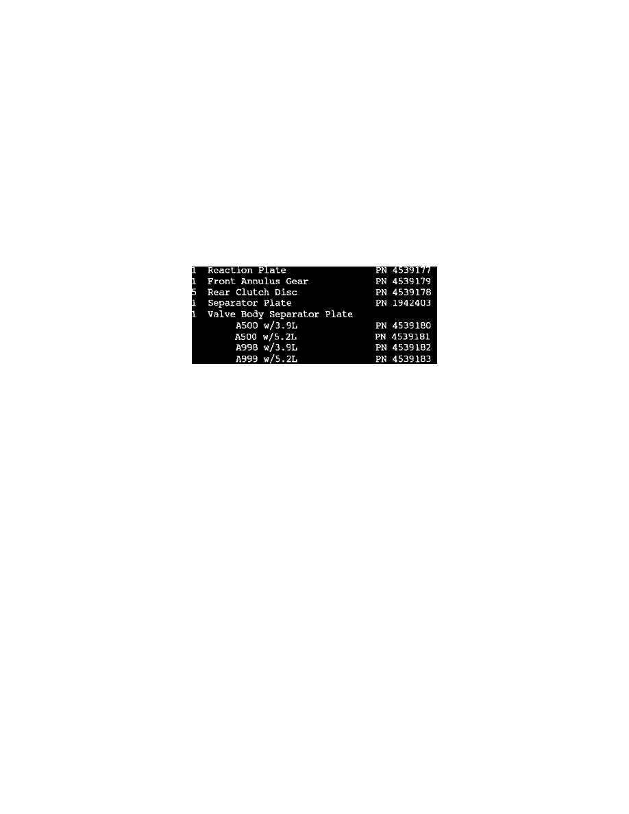
PARTS REQUIRED
REPAIR PROCEDURE
This procedure outlines the proper method to correct automatic transmission harsh engagement problems.
1.
Check and correct the following before proceeding with a transmission repair:
A.
Check engine idle speed as specified on the emission label.
B.
Inspect the motor mounts for damage, loose fasteners or misassembled components.
C.
Inspect the propeller shaft and rear axle assembly for excessive backlash.
D.
Inspect the rear springs for loose U-bolts and loose or misassembled hangers.
If no deficiencies are found, continue with the following procedure.
2.
Using the appropriate Service Manual, remove the transmission from the vehicle.
3.
Following the Service Manual procedure, remove the valve body assembly.
4.
Disassemble the valve body so that the valve body separator plate may be removed. Discard this plate and replace it with the appropriate plate
listed under PARTS REQUIRED. This new separator plate has a .110" diameter orifice to feed transmission fluid to the rear clutch.
5.
Reassemble the valve body. All screws must be torqued to Service Manual specifications.
6.
Following the Service Manual procedures, remove the rear clutch assembly from the transmission.
7.
Replace the clutch discs with the 5 new discs listed above. These discs have a different friction material and must be used for this package to work
properly. Note that the new clutch pack will have one more disc than the original clutch pack. This will require one more separator plate (PN
1942403) as shown in PARTS REQUIRED.
8.
Replace the reaction plate with the new part listed above (PN 4539177). The stepped side of the plate faces away from the clutch pack.
9.
The rear clutch pack clearance should be set at .03511 to .050" by using the appropriate selective snap ring. This is an increase in the clearance
from what is specified in the Service Manual and is required to improve the performance of the clutch.