
W350 1 Ton Pickup 4WD V8-360 5.9L VIN 1 4-bbl (1988)
Generator: Testing and Inspection
Chrysler Alternator & Regulator
Alternator Output Wire Resistance Test
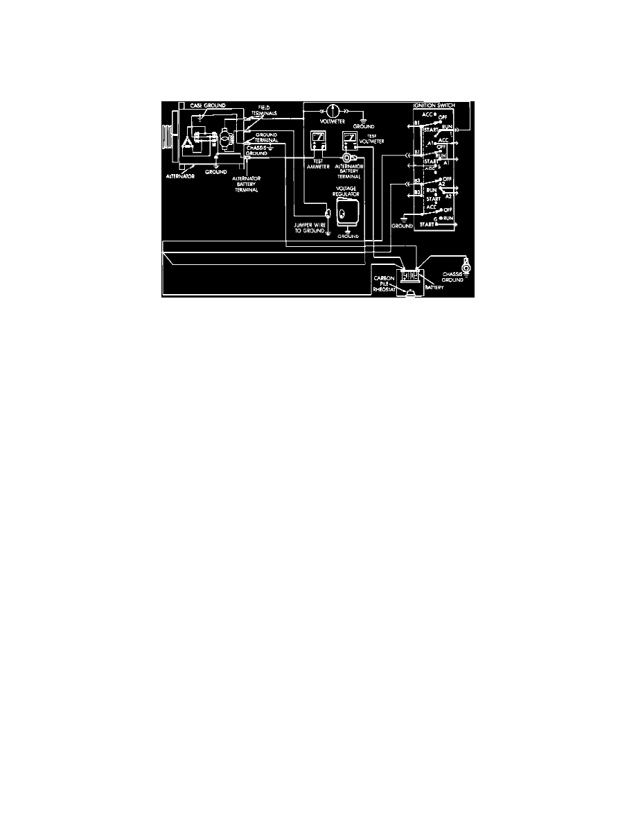
Fig. 1 Alternator output wire resistance test (Typical)
TESTING
1.
Disconnect battery ground cable.
2.
Disconnect "Bat" lead at alternator output terminal.
3.
Connect a 0-150 amp D.C. ammeter in series between alternator "Bat" terminal and disconnected "Bat" lead wire.
4.
Connect positive lead wire of a suitable voltmeter to disconnected "Bat" lead wire, then connect negative lead to battery positive post.
5.
Disconnect voltage regulator wiring connector, then using suitable jumper wire, connect wiring connector green regulator field wire to a suitable
ground. Do not connect blue J2 lead or wiring connector to ground. Do not spread connector terminals with jumper wire.
6.
Connect a suitable engine tachometer, then reconnect battery ground cable.
7.
Connect a variable carbon pile rheostat to battery terminals, ensuring carbon piles are in Open or Off position.
8.
Start engine and operate at idle speed, then adjust carbon pile and engine speed to maintain a 20 amp circuit flow. Note voltmeter reading.
Voltmeter reading should not exceed .5 volt.
TEST RESULTS
1.
If a higher than specified voltage drop is indicated, clean and tighten all connectors in charging circuit. A voltage drop test may be performed at
each connector to locate point of excessive resistance.
2.
If charging circuit resistance test was satisfactory, disconnect battery ground cable, then the ammeter, voltmeter and carbon pile.
3.
Remove jumper wire, then connect regulator wire connector.
4.
Connect battery ground cable.
Current Output Test