
W350 1 Ton Pickup 4WD V8-360 5.9L VIN 1 4-bbl (1988)
10.
Insert progressively thicker shims between arbor and gauge block, until fit of shim is snug but not excessively tight, then record thickness of shim.
11.
Inspect head of pinion for pinion depth modification code and select shim as follows: To ensure proper tooth contact, pinion may be marked
with a plus (+) or minus (-) code number, indicating in thousandths of an inch necessary modifications to the "nominal" depth setting. It
is essential that this modification code be factored when selecting pinion depth adjusting shim.
a.
If pinion is marked with a minus ( - ) code, add that number of thousandths to dimension obtained in step 10, and select shim thickness equal
to sum.
b.
If pinion is marked with a plus (+) code, subtract that number of thousandths from dimension obtained in step 10 and select shim thickness
equal to remainder.
12.
Remove gauge tool and adapter assemblies from housing and pinion bearings from shaft.
13.
Retain selected shim for pinion installation.
DRIVE PINION, INSTALL
1.
Install bearing races, and bearing race shims if equipped.
2.
Install selected depth adjusting shim on pinion.
3.
Press rear bearing onto pinion using suitable spacer to ensure bearing is fully seated.
4.
Install new collapsible spacer on pinion, lubricate pinion bearings, then insert pinion assembly into housing.
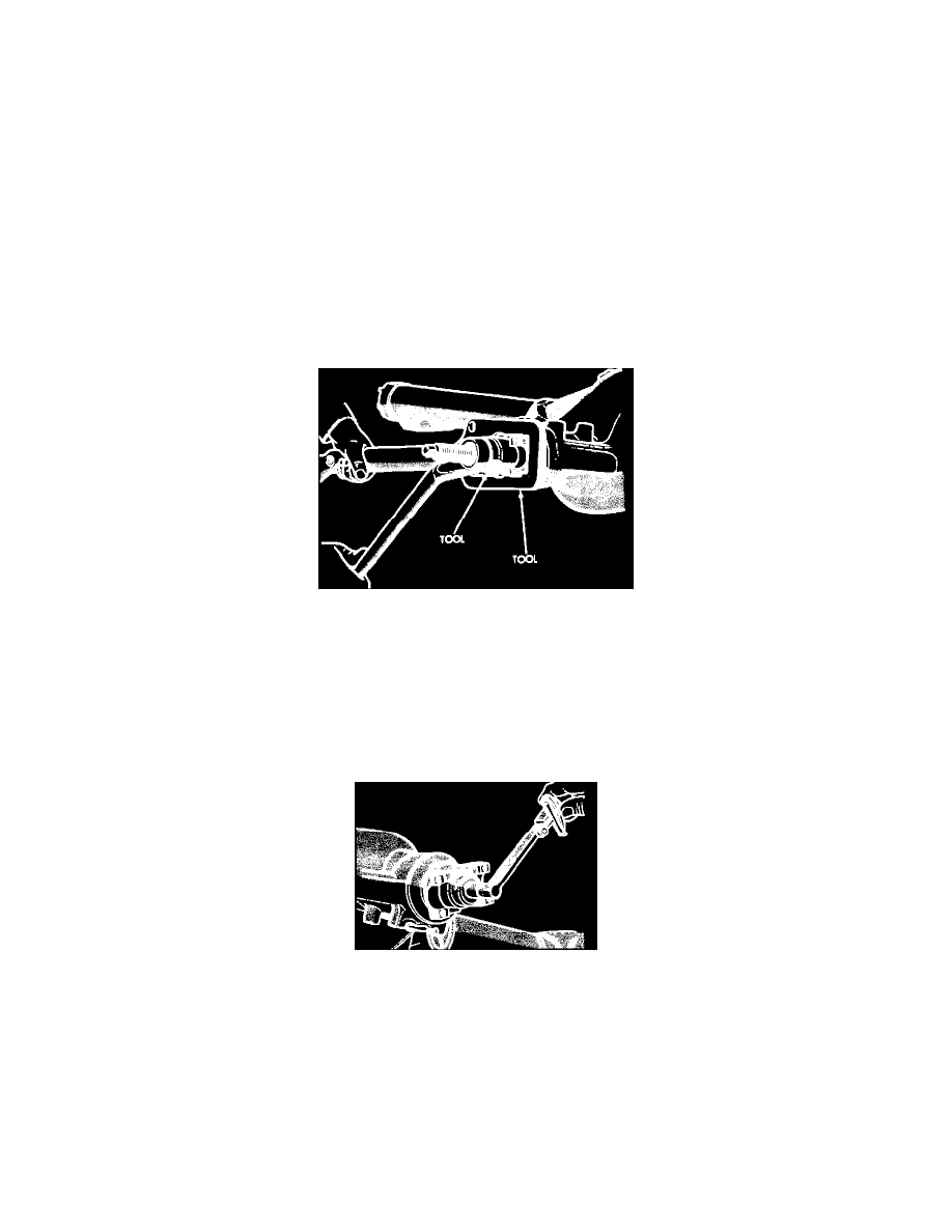
Fig. 21 Companion flange & front pinion bearing installation
5.
Install front pinion bearing, companion flange and forcing tool on pinion. Use tool C-3718 on models with 8-3/8 inch ring gear, C-496 on models
with 9-1/4 inch ring gear or suitable equivalents.
6.
Hold companion flange and tighten nut on forcing tool to seat front bearing on pinion shaft. Care must be taken not to collapse spacer when
seating front bearing on pinion shaft. Tighten tool only until endplay has been eliminated.
7.
Remove forcing tool and companion flange, then install new pinion seal using suitable driver.
8.
Lubricate lips of pinion seal, then reinstall companion flange using forcing tool as outlined in steps 5 and 6.
9.
Remove forcing screw, then install washer and new pinion nut.
Fig. 8 Measuring pinion rotating torque (bearing preload)
10.
Hold companion flange and torque pinion nut to 210 ft. lbs., then check bearing preload using suitable torque wrench. Bearing preload must be
within specifications with pinion nut torqued to a minimum of 210 ft. lbs. If bearing preload is greater than specified at minimum torque
specification, or if preload is not even through full rotation, recheck pinion installation, replace collapsible spacer and repeat adjustment.
11.
If bearing preload is less than specified, continue tightening nut in small increments, checking preload after each adjustment. If specified preload
is exceeded, spacer will be collapsed too far to be reused. Spacer must be replaced and adjustment procedure must be repeated. Do not
loosen pinion nut to reduce preload.