
W350 1 Ton Pickup 4WD V8-360 5.9L VIN W 4-bbl (1983)
INSTRUMENT PANEL WIRING
4.
Route the instrument panel overlay harness along the existing instrument panel ignition switch wiring from the bulkhead connector and
behind the fuse block to the existing red mold connector and instrument panel ground terminal (Figure 2-C).
Secure the instrument panel overlay harness using the existing wiring clip that retains the ignition switch wiring and one tie wrap, PN
6015756 (Figure 2-C).
5.
Install the female blade terminal (white with black tracer wire) from the instrument panel overlay harness onto an instrument panel ground
terminal located to the right of the steering column (Figure 2-C).
6.
Insert the bare terminal (light blue wire) from the instrument panel overlay harness into the existing 3-way red molded connector, from the
main instrument panel wiring harness, (Located near radio, Figure 2-C).
INSTRUMENT PANEL WIRING
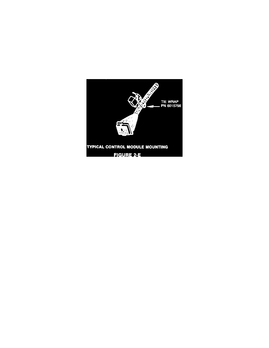
7.
Connect the control (auto shut down) module, PN 5226640, to the supplied natural colored 8-way connector from the instrument panel
overlay harness, PN 4362284. Secure the module onto the main instrument panel wiring harness with a tie wrap, PN 6015756, close to the
bulkhead connector (Figure 2-E).
C.
In-Tank Fuel Pump Installation
1.
Remove the fuel tank gauge unit from the fuel tank per the service manual procedure and discard. Install the new seal and gauge/pump unit
from the applicable kit. Use extreme caution to protect the float and gauge assembly during installation into the fuel tank.
2.
With the fuel tank partially raised, connect the fuel tank vent hose, fuel return, and fuel supply hoses. Secure the hoses with the hose
clamps provided.
3.
Install existing gauge/pump wiring:
^
Black mold connector (gauge circuit) light blue with tracer wire to black stud of gauge/pump assembly.
^
Tape back existing yellow mold connector white wire (this wire will no longer be used).
^
Install red mold connector (pump feed circuit) dark green wire of new body wiring overlay harness, PN 4362286, onto the red stud
of gauge/pump assembly.
^
Install yellow mold blade connector of body overlay harness, PN 4362286, to ground blade on gauge/pump assembly.
CAUTION:
INCORRECT WIRING CONNECTIONS WILL CAUSE THE FUEL LEVEL GAUGE UNIT AND/OR
CLUSTER GAUGE TO FAIL AND THE ELECTRIC PUMP TO BE INOPERATIVE.
^
Set aside the rest of harness, PN 4362286, to assure wiring is not pinched when reinstalling fuel tank.
4.
Reinstall fuel tank to original position.