
W350 1 Ton Pickup 4WD V8-360 5.9L VIN W 4-bbl (1983)
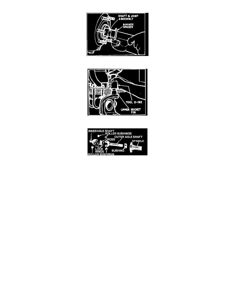
Fig. 21 Removing or replacing axle shaft. 60 Front Axle
Fig. 22 Removing or replacing upper socket pin. 60 Front Axle
Fig. 23 Universal joint, spindle and bushing assembly. (Typical)
1. Block brake pedal in "Up" position.
2. Raise and support vehicle.
3. Remove wheel.
4. Remove brake caliper from adapter and, using a piece of wire, suspend caliper. Do not hang caliper by brake hose. The inner brake pad will
remain on adapter.
5. Remove hub cap and snap ring.
6. Remove flange nuts and lock washers.
7. Remove drive flange and discard gasket, or remove locking hub, if equipped.
8. Straighten tang on lock ring, then remove outer locknut, lock ring, inner locknut and outer-bearing. Slide hub and rotor assembly from spindle.
9. Remove inner brake pad from adapter.
10. Remove nuts and washers securing brake splash shield, brake adapter and spindle to steering knuckle.
11. Remove spindle from knuckle. Slide inner and outer axle shaft with bronze spacer, seal and slinger from axle.
12. Remove cotter key and nut from tie rod. Disconnect tie rod from steering knuckle.
13. On left side only, remove cotter key and nut from drag link. Disconnect drag link from steering knuckle arm. Also, remove nuts and upper knuckle
cap. Discard gasket. Remove spring and upper socket sleeve.
14. Remove capscrews from lower knuckle cap and free cap from knuckle and housing.
15. To remove knuckle from housing, swing outward at bottom, then lift up and off upper socket pin.
16. Using a suitable tool, loosen and remove upper socket pin, then the seal.
17. Press lower ball socket from axle housing with suitable tools.
18. Disassemble shaft.
Assembly & Installation