
W 350 Pickup V8-5.9L VIN Z (1990)
Automatic Shut Down (ASD) Relay: Testing and Inspection
Main Relay testing and inspection can also be found at Powertrain Management / Computers and Control systems / Testing and Inspection / Procedures /
Diagnostic Charts / No Start (NS) Tests / NS-14 Repairing Fault "ASD Relay Circuit".
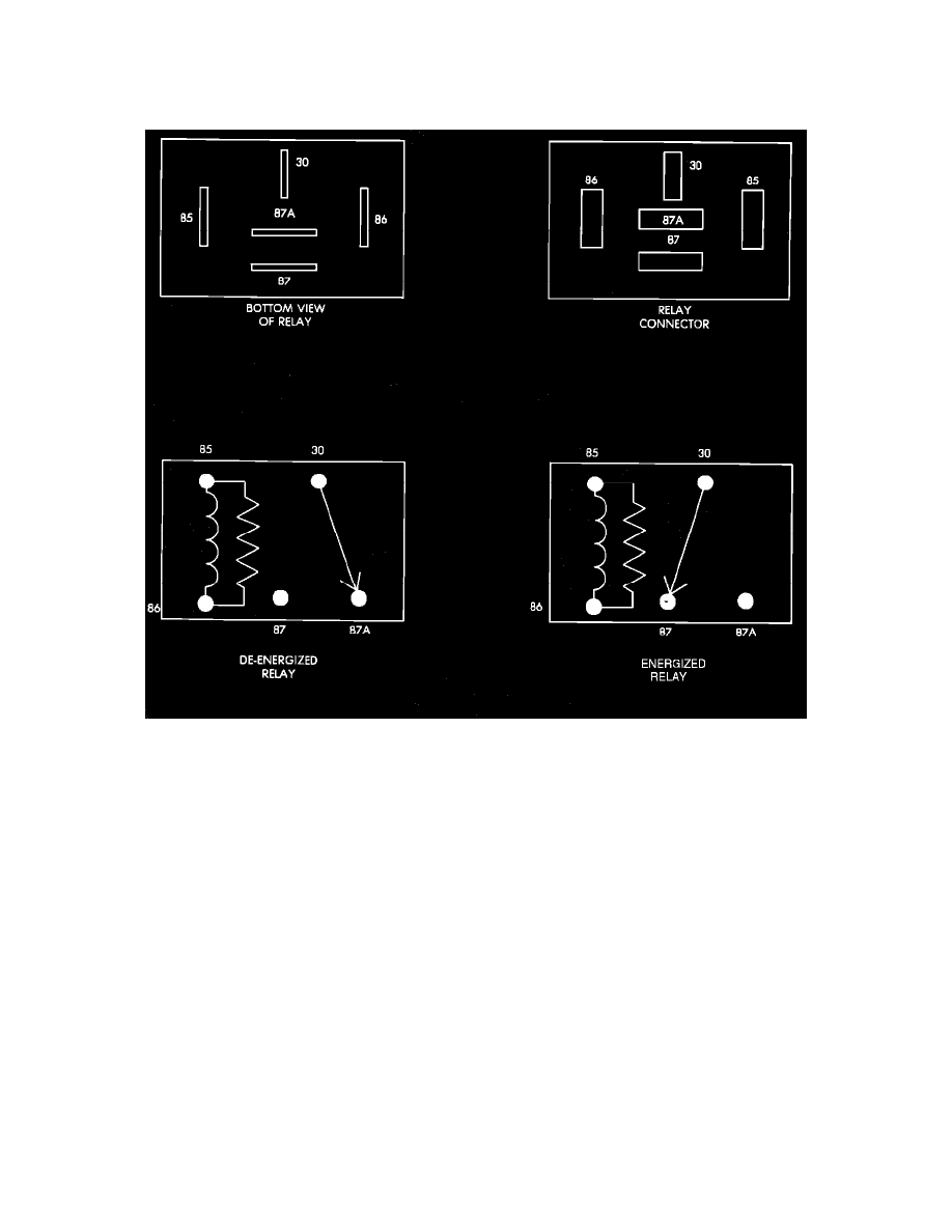
Relay Terminal Identification
ASD RELAY TERMINAL IDENTIFICATION
The following is a list of the terminal numbers, with circuit codes, and color codes, and their function:
Circuit No. Terminal No.
Color Code
Description
J1/J11
30
Red
Has battery input voltage supplied through fusible link.
Z1
87
Green/blk.
Connected to J1 circuit (terminal 30) in the energized position, supplies output voltage to fuel pump, O2
sensor, fuel injectors, and coil.
J2
86
Blue/wht.
Connected to the electromagnet, (diode) and the Single Board Engine Controller (SBEC). The SBEC
provides input voltage to relay.
K19
85
Blue/yel.
Connected to the electromagnet (diode) and grounded by the SBEC when distributor signal is present.
N/A
87A
N/A
Not used in these applications.
ASD RELAY TEST
NOTE: The ASD relay operation may be tested with the use of the DRB II scanner or equivalent. Refer to COMPUTERIZED ENGINE
CONTROLS/DIAGNOSIS AND TESTING for procedure. If no scanner is available proceed with the following test.
1.
Connect a voltmeter to the J1 (terminal 30) wire at the ASD connector. Check for battery voltage. If no voltage is present, check fusible links and
supply voltage from the battery. If voltage is present proceed to step 2.