
Eagle L4-150 2.5L (1983)
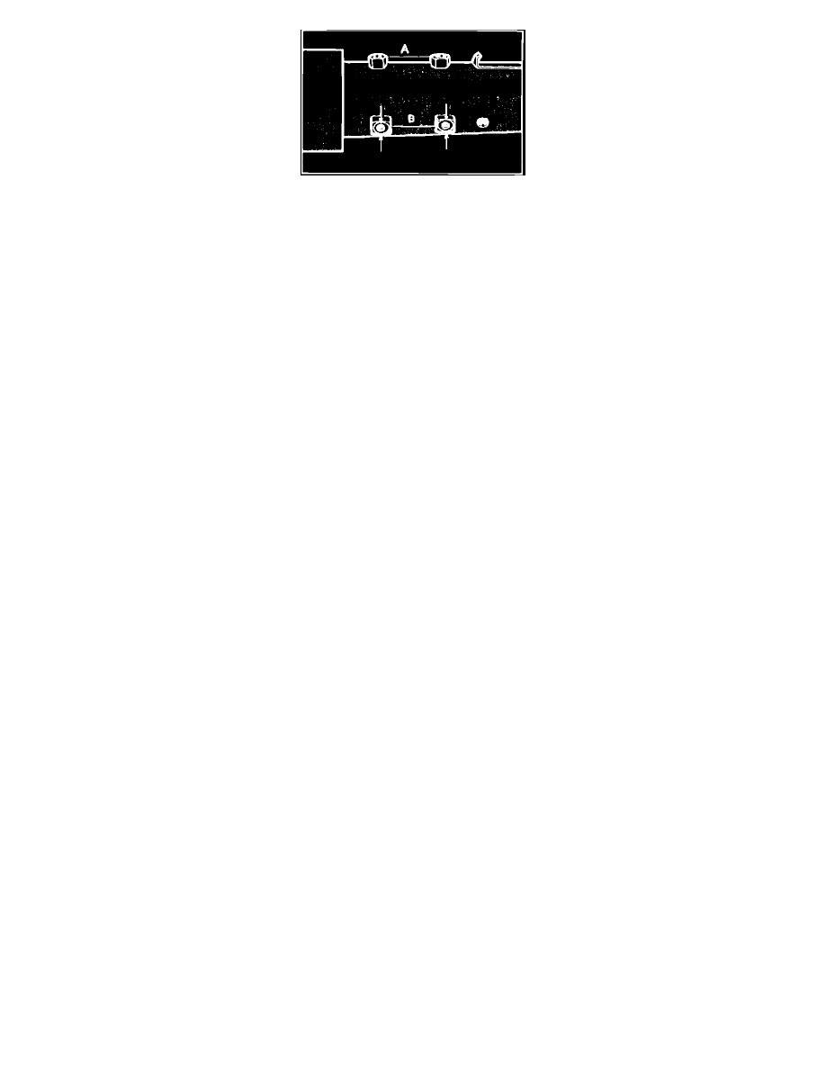
Fig. 29 Steering column clamping points
1. Remove dash panel bracket and store bracket in a safe place to prevent damage to mounting capsules.
2. Place column in a vise using both weld nuts of either set A or B. The vise jaws must clamp onto the sides of weld nuts indicated by arrows shown
on set B. Do not place column in vise by clamping onto only one weld nut, by clamping on one weld nut of both sets A and B or by
clamping onto the sides not indicated by arrows, as damage to column could result.
3. Inspect steering shaft to determine type of thread used for steering shaft nut. Metric type shafts can be identified by a groove located in area of
steering wheel locating splines, while shafts with American type threads do not have this groove. If shaft has metric type threads, the forcing screw
of Lock Plate Compressor Tool J-23653 must be removed and replaced with the metric forcing screw J-23653-4 before installing lock plate
compressor tool on steering shaft. Compress lock plate using lock plate compressor tool, then pry snap ring from shaft groove and discard wing.
Remove lock plate compressor tool and lock plate.
4. Remove directional signal switch, lock cylinder and ignition key warning switch, then remove steering shaft from lower end of column.
5. On power steering columns, remove steering shaft lower bearing from plastic adapter at lower end of column.
6. Remove four turn signal housing to column jacket retaining screws and remove housing and shroud assembly.
7. Remove three shroud to signal housing retaining screws and remove shroud.
8. Using hand as shield to prevent lock inhibitor lever spring wire from flying out, remove lock inhibitor lever and spring wire.
9. Lift ignition switch actuating rod, rack assembly, shaft lock bolt and spring assembly from housing, then if necessary, remove rack preload spring.
10. Remove ignition switch actuator sector through lock cylinder hole by pushing firmly on block tooth of sector with a blunt punch or screwdriver.
Assembly
Prior to assembly, apply a light coat lithium soap grease to all friction surfaces.
1. Install sector into turn signal housing, then reaching through lock cylinder hole, place sector onto shaft with tang end to outside of hole and press
sector onto shaft using a blunt tool.
2. If rack preload spring was removed, insert spring into housing from lower end, hooking onto edge of housing at both ends.
3. Assemble locking bolt onto crossover arm on rack, making certain that lock bolt spring and plastic washer are in place. Insert rack and lock bolt
assembly into housing from bottom with teeth facing up toward centerline of column. Align first tooth on sector with first tooth on rack. If aligned
properly, the block tooth will line up when the rack assembly is pushed all the way in.
4. Place lock inhibitor spring wire over lever on pivot housing, then install lever in place with tang behind rack and with spring wire hooked onto the
lever. While holding down at pivot point of lever, hook other end of wire into slot provided in housing so that lever is flush with top of pivot.
5. Place shroud over ignition switch actuating rod and onto the housing, then install three retaining screws and torque to 60 inch lbs.
6. Install turn signal housing assembly over upper end of column assembly, then install the four retaining bolts and torque to 60 inch lbs.
7. On power steering columns, press new steering shaft lower bearing into plastic adapter at lower end of column.
8. Install steering shaft into lower end of column and guide it up through the upper bearing, then install ignition switch, ignition key warning switch,
lock cylinder and directional signal switch. On manual steering columns, there will be about 1 3/16 inch clearance between lower end of column
and clamp on shaft. Do not move clamp to eliminate this clearance.
9. Install dash panel bracket and torque the four mounting screws to 19 ft. lbs. Make certain that slotted openings in bracket (for mounting
capsules) face upper end of steering column.