
Eagle Sedan L6-258 4.2L (1984)
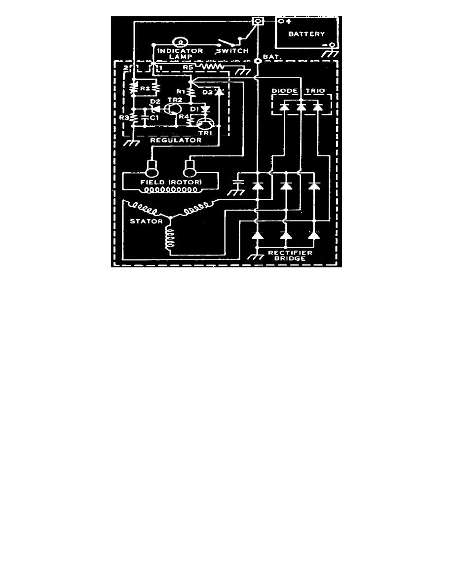
Fig. 3 Typical wiring diagram of charging circuit
These units feature a solid state regulator mounted inside the alternator slip ring end frame, along with the brush holder assembly. All regulator
components are enclosed in a solid mold with no need or provision for adjustment of the regulator. A rectifier bridge, containing six diodes and
connected to the stator windings, changes A.C. voltage to D.C. voltage which is available at the output terminal. Generator field current is supplied
through a diode trio which is also connected to the stator windings. The diodes and rectifiers are protected by a capacitor which is also mounted in the
end frame.
General Motors units incorporate a resistor in the warning indicator circuit.
Some alternators used on diesel engines are equipped with an R terminal for the tachometer. On these units, if the alternator pulley is to be replaced, a
pulley of the same diameter as the one removed must be installed, otherwise tachometer may provide inaccurate readings.
No maintenance or adjustments of any kind are required on this unit.