
Medallion L4-2165cc 2.2L (1988)
10.
Locate the green wire (N of Figure 6) leading to terminal "C" of the MAP sensor connector (M).
11.
Cut the green wire (N) 1-1/2 inches from the connector.
12.
Remove 1/2 inch of insulation from each end of the cut wire
(N)
with a wire stripper tool.
FIGURE 7
13.
Slide the heat shrink tubing from the kit onto the voltage source wire (E of Figure 7). Then slide the tubing back from the wire end about two
inches to avoid heating the tubing when the wire is soldered.
14.
Twist the ends of wire (N) together. Then twist the end of wire (E) around wires (N) to ensure a strong connection (Figure 7).
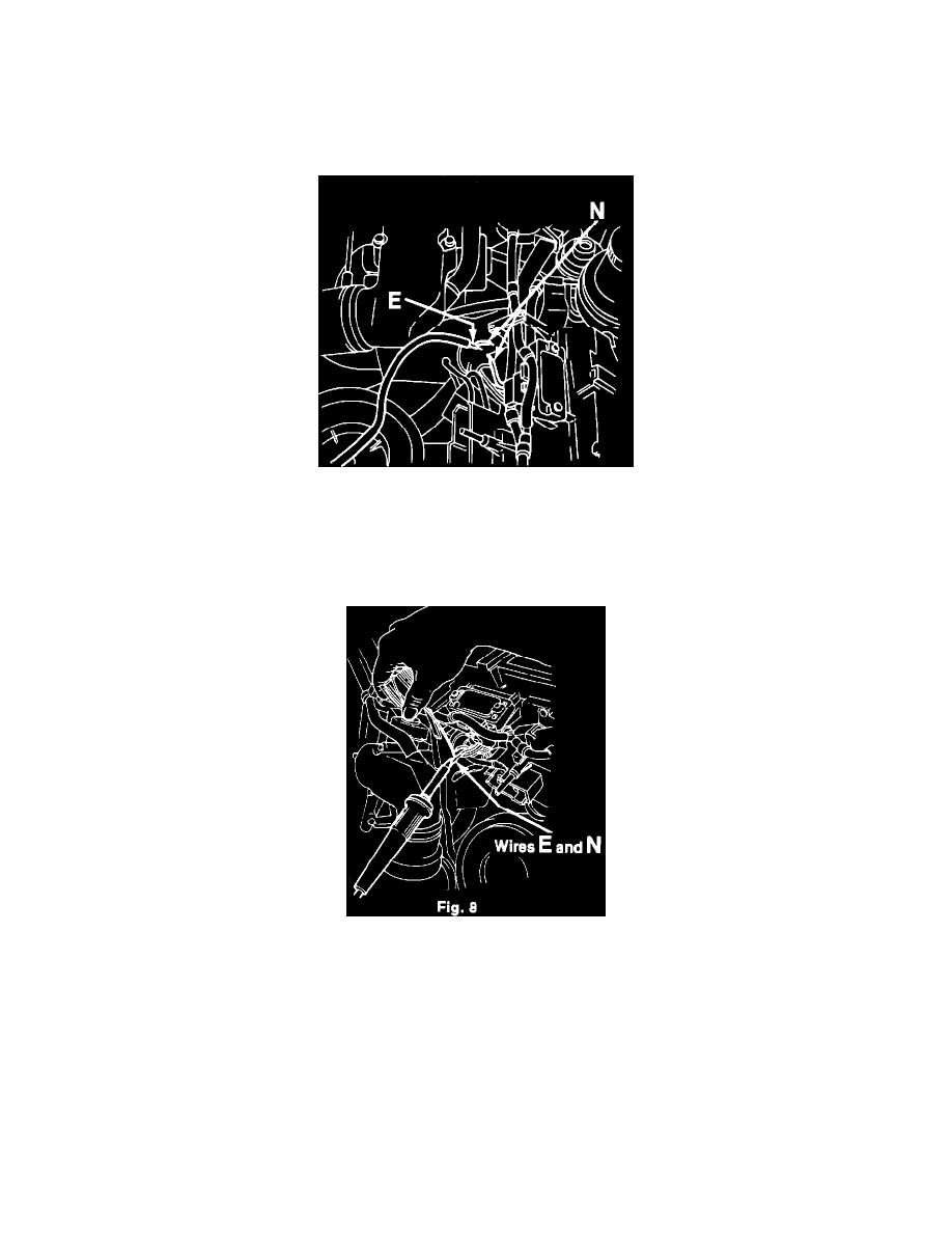
FIGURE 8
8804 - Driveability -- Manual Transmission Equipped Models
^
Kit Installation Procedure (Continued)
15.
Solder wires (E) and (N )together with rosin core solder (Figure 8).
16.
Slide the heat shrink tubing over the soldered connection. Be sure that the tubing completely covers the solder joint and any sections of bare
wire.