
Medallion L4-2165cc 2.2L (1988)
Cylinder Liner: Service and Repair
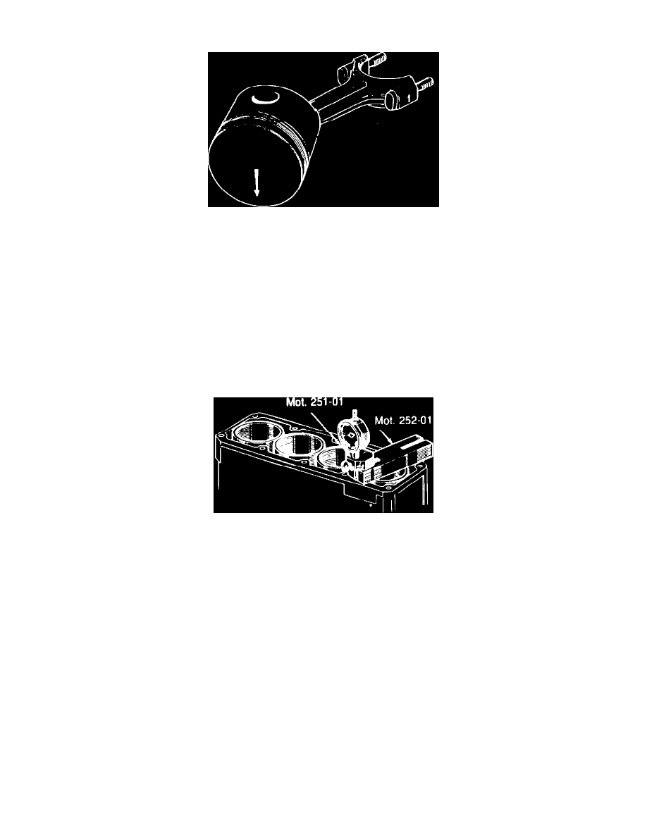
Fig. 31 Piston & rod identification marks
The pistons and liners are serviceable without removing the engine from the vehicle. Pistons and liners are available in standard size only and are
matched sets. Do not mix the pistons or liners during assembly.
To remove the piston assemblies, remove the head and oil pan. Check the rods for numbering. If necessary, mark sides of the rods facing away from
the camshaft. No. 1 cylinder is located next to the engine flywheel/flexplate.
Using a press to press the piston pin, mount the pistons to the rods with the arrow on the piston facing toward the flywheel and the mark on the
connecting rod, made during disassembly, facing away from the camshaft, Fig. 31.
Liner protrusion must be checked prior to the final assembly of the piston and liners in the block. The liners must protrude slightly above the block to
insure proper sealing by the head gasket and the head. All engine blocks are fitted with O-rings for sealing. Liner protrusion cannot be changed in
blocks fitted with O-rings. However, the protrusion should be checked to ensure proper cylinder and head sealing.
Fig. 32 Checking cylinder liner protrusion
CHECKING LINER PROTRUSION
1. Install liners in block without O-ring seal.
2. Install dial indicator in gauge block Mot. 251.01 and tighten screw clamp, Fig. 32.
3. Place thrust plate Mot. 252.01 across each cylinder liner, Fig. 32, and measure liner protrusion above block with dial indicator.
4. If liner protrusion is not within specifications, measure protrusion of replacement liner to determine whether liner or cylinder block is defective,
and replace components as needed.
5. When protrusion of all liners is within specifications, arrange liners so that the difference in protrusion between adjacent liners does not exceed
0.002 inch (0.04 mm), and so that the protrusions are stepped down from the No. 1 cylinder to the No. 4 cylinder.
6. After the liner protrusion has been checked, remove the liners from the block and assemble the piston, rod and liner assemblies as outlined.
PISTON & LINER ASSEMBLY
1. Install new O-ring seal onto each liner, ensuring O-ring is not twisted.
2. Assemble pistons, rods, piston rings and bearing inserts, noting matching marks and installation position.
3. Lubricate the pistons and rings with engine oil.
4. Compress rings with suitable tool and insert piston and connecting rod assemblies through bottom of liner, ensuring machined sides of the
connecting rod bearing end are parallel with the flat edge on the top of the liner.
5. Lubricate connecting rod journals and bearing inserts in connecting rod and cap, then install the piston liner assemblies into the block. Ensure
O-ring is not twisted. Mount as follows:
a. Number 1 piston at the flywheel/flexplate end.
b. Number on the connecting rod facing away from the camshaft.