
Medallion L4-2165cc 2.2L (1988)
Throttle Position Sensor: Adjustments
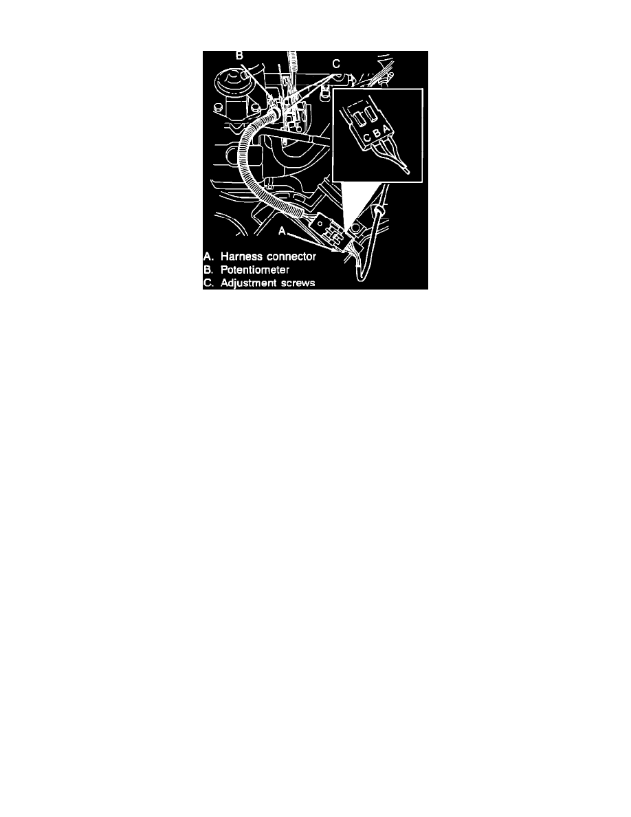
Fig. 1 Harness connector, throttle position sensor (potentiometer) & adjustment screw assembly
To perform the TPS adjustment procedure, diagnostic tester MS 1700 or equivalent is required.
1. Verify that the throttle is completely opened when the accelerator pedal is fully depressed.
2. Turn ignition switch to ON position.
3. Check TPS input voltage using a suitable digital volt-ohmmeter as follows:
a. Insert negative lead of volt-ohmmeter into terminal C of TPS harness connector and positive lead into terminal B of harness connector, Fig.
1. Do not disconnect the harness connector. Insert the leads into the end of the connector and push them inward to contact the
terminals.
b. Move throttle plate to the wide open position and not voltage reading. Input voltage should be approximately 4.3 volts.
c. Return the throttle plate to the closed position.
d. Remove positive lead from harness connector terminal B and insert it into terminal A.
e. Move the throttle plate to the wide open position, then note and record voltage reading obtained.
f.
Output voltage should be approximately 4 (plus or minus .5 percent) of the input voltage.
g. Return throttle plate to the closed position and determine required TPS output voltage.
4. To determine the required TPS output voltage, note example:
a. Recorded input voltage was 4.2 volts.
b. 4.2 volts x 4 percent, equals an output voltage of .168 volts.
c. 4.2 volts x .5 percent, equals an output voltage range variance of plus or minus .021 volts.
d. Output voltage should be .168 volts plus or minus .021 volts which equals a variance range of .147-.189 volts.
5. To adjust output voltage, proceed as follows:
a. Block throttle linkage in the wide open position.
b. Loosen TPS adjustment screws.
c. Rotate TPS upward or downward to obtained required output voltage.
d. Tighten TPS screws and check voltage readings. Adjust, if necessary.