
Medallion L4-2165cc 2.2L (1988)
Valve Clearance: Adjustments
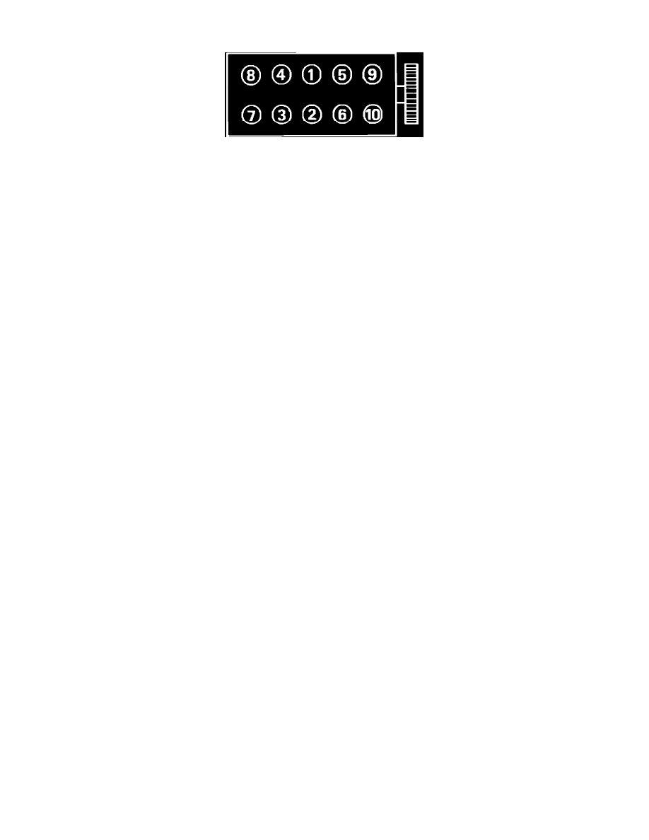
Fig. 5 Cylinder head tightening sequence
1.
Rotate crankshaft clockwise until camshaft sprocket TDC mark is aligned with timing belt cover front window. Ensure piston is at TDC. Piston
No. 1 is located at the flywheel/flexplate side of cylinder head.
2.
Continue to rotate crankshaft clockwise (viewed from front of engine) until camshaft sprocket first mark B, is aligned with the index mark in the
timing belt cover rear window.
3.
With first mark aligned as outlined in step 2, adjust cylinder No. 2 intake valve and cylinder No. 4 exhaust valve.
4.
Continue to rotate crankshaft clockwise (viewed from front of engine) until camshaft sprocket second mark is aligned with the index mark in the
timing belt cover rear window.
5.
With mark aligned as outlined above, adjust cylinder No. 1 intake valve and cylinder No. 2 exhaust valve.
6.
Continue to rotate crankshaft clockwise (viewed from front of engine) until camshaft sprocket third mark is aligned with the index mark in the
timing belt cover rear window.
7.
With mark aligned as outlined above, adjust cylinder No. 3 intake valve and cylinder No. 1 exhaust valve.
8.
Continue to rotate crankshaft clockwise (viewed from front of engine) until camshaft fourth mark is aligned with the index mark in the timing belt
cover rear window.
9.
With mark aligned as outlined above, adjust cylinder No. 4 intake valve and cylinder No. 3 exhaust valve.