
Medallion L4-2165cc 2.2L (1988)
to its connector.
2.
Remove the connector from the B+ latch relay.
FIGURE 3
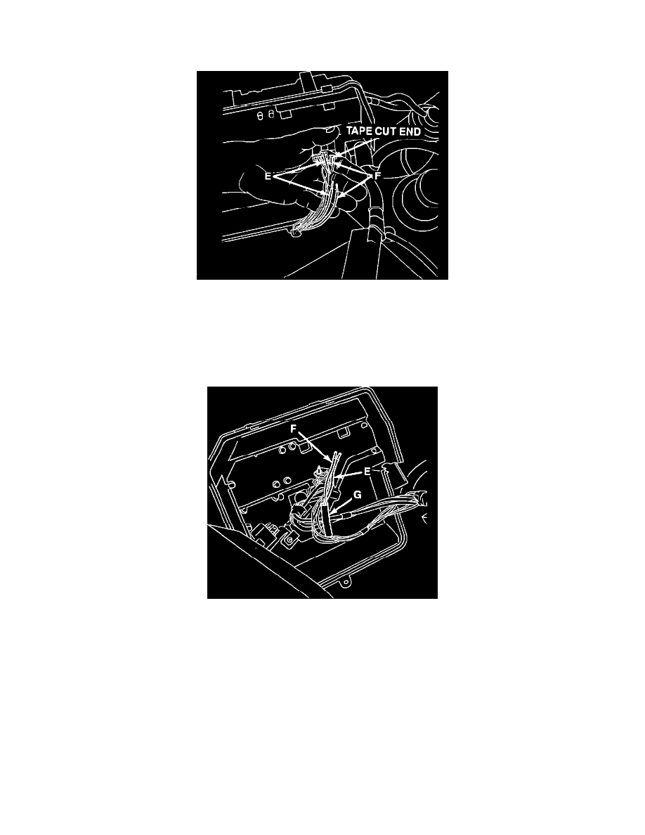
3.
Cut the yellow w/trace wire (E) approximately 1 1/2 inches back from B+ latch relay connector. Strip 1/2 inch of insulation from both ends of the
cut wire. See Fig. 3.
4.
Cut the small (20 gauge) brown wire (F) 1/2 inch from the B+ latch relay connector and carefully tape the connector end of the cut wire. Strip 1/2
inch of insulation from the harness end of the cut wire. See Fig. 3.
FIGURE 4
5.
Hold the harness end of the brown wire (F) parallel to the yellow w/trace wire (E), and slide 1-1/2 inches of heat shrink tubing (G) over the ends
and down the wires about 2 inches to avoid damage during the soldering process. See Fig. 4.
6.
Twist the end of the brown wire (F) and the two ends of the previously cut yellow w/trace wire (E) together tightly. See Fig. 4.