
Medallion L4-2165cc 2.2L (1988)
Crankshaft Position Sensor: Description and Operation
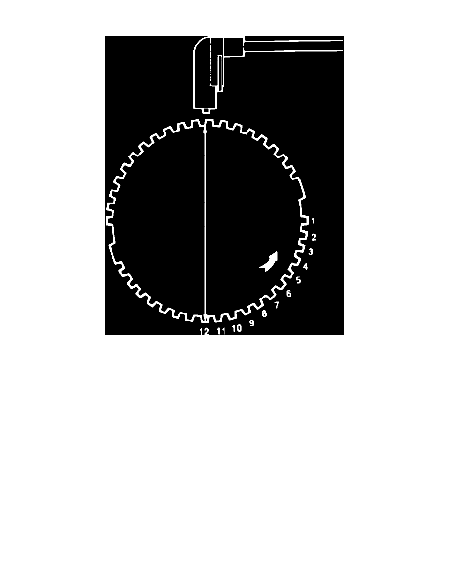
Fig. 1 Engine speed sensor & flywheel
This sensor is mounted on the flywheel housing. By detecting the passing of various small and two large (trigger) teeth on the flywheel, Fig.1, this
sensor is able to send engine speed and crankshaft angle information to the ECU. The two trigger teeth provide information 90 degrees before and after
TDC. Because the sensor is a magnetized component, the force of the magnetic field increases as the trigger teeth approach the speed sensor magnet, and
is at its maximum strength when the teeth are in direct alignment with the sensor. When the field strength is increasing at its most rapid rate, a voltage is
induced in the sensor inductive pickup coil. As the trigger tooth passes and moves away from the sensor, the magnetic field collapses, inducing a voltage
signal which is then sent to the ECU. Weaker voltages are generated each time one of the smaller teeth pass the sensor. These voltages allow the ECU to
count the passing teeth. Because the ECU knows that TDC occurs 12 teeth (90 degrees) after the trigger tooth, it can adjust ignition timing as required by
counting the passes of the smaller teeth