
Medallion L4-2165cc 2.2L (1988)
Constant Velocity Joint Boot: Service and Repair
Constant Velocity Joint & Boot Service
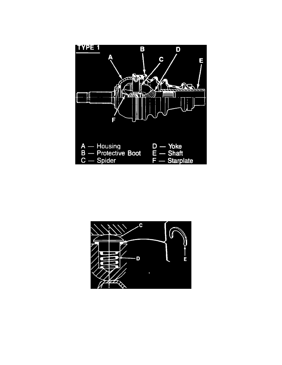
Type 1 Outer C/V Joint
Fig. 3 Sectional view of type 1 constant velocity joint
Disassembly
1. Remove driveshaft.
2. Cut, then remove boot clamps.
3. Slide boot away from joint and remove as much grease as possible from constant velocity joint. Do not use cleaning solvents.
4. Using a suitable screwdriver, lift star plate tabs upward to release the yoke from the spider. Do not bend the tabs.
5. Remove yoke and shaft from constant velocity joint.
Fig. 4 Removing thrust ball (C), spring (D) & shim (E). Type 1
6. Remove and retain the thrust ball (C), spring (D) and shim (E) from the spider.
7. Cut the boot in half and remove it from the shaft.
8. Remove all grease from constant velocity joint. Do not use cleaning solvents.
Assembly
1. Install shaft into a suitable vise. Position shaft so yoke is pointing upward. Do not attempt to install the boot without using the proper tool for
that purpose. The boot can be damaged.
2. Install expander tool T.Av.586.01 or equivalent onto shaft yoke.