
Premier L4-150 2.5L (1988)
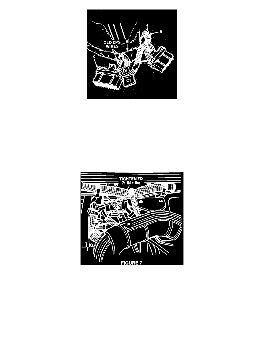
FIGURE 6
12.
Remove the red w/green tracer wire labeled D1 from the D1 cavity and insert the red w/green tracer wire labeled D1 from the from the CPS patch
harness into the D1 cavity of the 32-way connector. Figure 6
13.
Cut the terminal end off the old D1 and C1 wires to prevent future use. Tape the two cut wires (M) back to the EEC harness. Figure 6
14.
Install the two wire locks (K) into their original positions on the 32-way connector. Figure 6
15.
Secure the CPS patch harness to the EEC harness with one tie strap (N). Figure 6
16.
Install both ECU connectors to the ECU and insure that all wire terminals and both connectors are fully engaged to the ECU.
17.
Install the ECU to the instrument panel with the three retaining nuts.
FIGURE 7
18.
Locate the EEC 34-way connector (P) on the engine side of the bulkhead and tighten connector bolt to 71 in.lbs (8 N-m) of torque. Figure 7
19.
Connect the battery negative terminal.
POLICY:
Reimbursable within the provisions of the warranty.
TIME ALLOWANCE:
Labor Operation No.
08-90-65-90 . . . . . . . . . 0.6 Hrs.
FAILURE CODE:
85 - Improperly Installed Wiring