
Spirit L6-258 4.2L VIN C 2-bbl (1982)
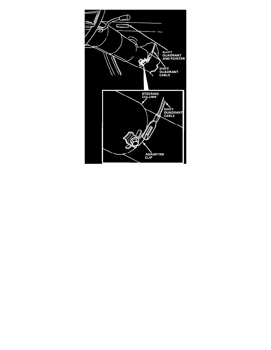
Fig. 2 Shift indicator control cable installation. Automatic transmission models w/column shift
1. Attach mounting bracket to column and torque bolts to 20 ft. lbs. If intermediate steering shaft was removed, install shaft aligning reference
marks made during disassembly.
2. Install column engaging flex coupling on steering shaft and loosely install two upper nuts to instrument panel and two toe plate screws.
3. Install flex coupling nuts and torque to 30 ft. lbs.
4. Position column so that flex coupling is flat and not distorted, then torque upper column mounting bolts to 10 ft. lbs.
5. If necessary, loosen toe plate clamp and position it against firewall, then install retaining screws and torque to 10 ft. lbs. On 1982 - 87 models,
align toe plate and clamp, and torque to 18 ft. lbs.
6. Connect shift linkage and quadrant cable and check for proper operation, then connect all electrical wiring and install trim panel and package tray.
On 1983 Eagle models, the steering gear flexible coupling bolts may contact the steering gear housing when making turns. This may result
in a hissing noise coming from the steering column as steering gear housing fluid flow noise is momentarily channeled to the steering
column. To eliminate this noise, realign the steering column flexible coupling as follows:
a. Remove driver door step plate and kick panel, then the accelerator pedal bracket and steering column lower trim cover.
b. Loosen toe board and steering column mounting bracket bolts.
c. Loosen flexible coupling bolts and steering gear mounting bolts.
d. Position gear as necessary to align steering gear stub shaft with steering column intermediate shaft. Torque steering gear mounting bolts to 65
ft. lbs. and flexible coupling bolts to 25 ft. lbs.
e. Pull or push steering wheel as necessary to align flexible coupling. When properly aligned, the coupling will be flat and level. If flexible
coupling is saucer shaped or distorted, it must be realigned.
f.
Torque steering column mounting bracket bolts to 10 ft. lbs. Inspect steering column flexible coupling to ensure proper alignment and that no
contact exists between coupling bolts and steering gear at any point during steering wheel rotation.
g. Torque toe board bolts to 10 ft. lbs., then install accelerator pedal bracket, steering column lower trim panel, kick panel and door step plate.
Disassembly
1. Remove column mounting bracket and wire protector and strip wires from protector. Do not damage wires. Unsnap connector from bracket
and tape wires to prevent snagging when removing switch.
2. Remove steering wheel, then loosen the three cover screws and lift cover from housing.
3. Remove tilt release lever and turn signal lever, then depress hazard warning knob and remove knob.
4. Using tool J-23653, depress lock plate and remove wire snap ring from groove shaft, then remove shaft lock, cancelling cam and upper bearing
spring.
5. Remove the three turn signal retaining screws and pull switch straight out while guiding wires through shroud.