
Summit L4-1468cc 1.5L SOHC (1989)
DRIVE GEAR:
1.
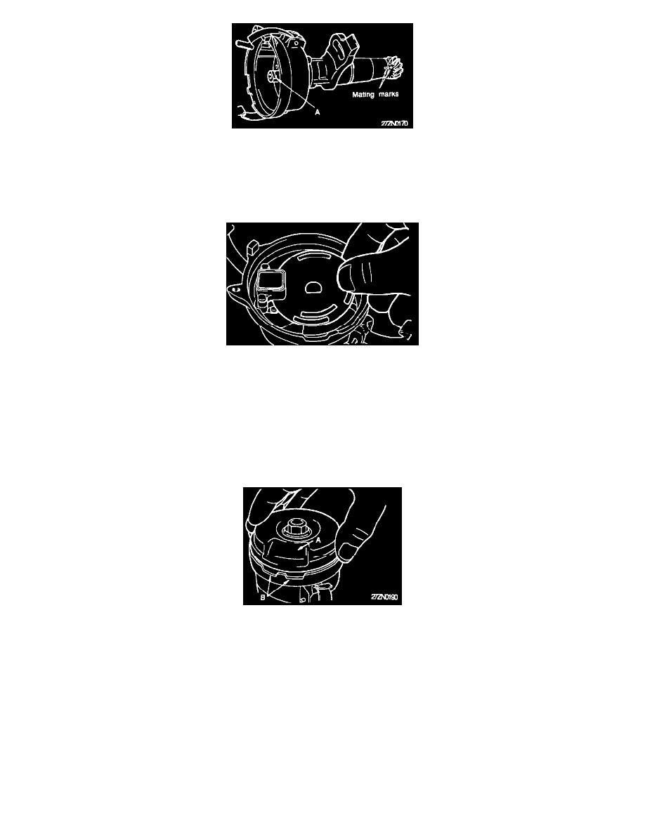
Align the drive gear with the mark made at the time of disassembly, and install the gear to the distributor shaft.
2.
When aligning the drive gear's mating mark to the housing's mark, be sure that the notch "A" at the rotor end of the shaft is in the position shown
in the (Distributor Assembly Marks) image. If no errors where made in either the marking or alignment procedures the pin holes should align
properly. Drive in a new roll pin, insuring that the slit in the pin is at 90° to the distributor shaft.
Disc Installation Procedure
DISC:
1.
Install the spacer on the distributor shaft.
2.
Insert the disc into the sensor part of the pick up unit assembly insuring the proper alignment with the notch on the spacer.
NOTE: Take care to install the disc with the correct side to the top as was observed during disassembly. Insure that the disc is clean and that the
disc's slits are clear of any foreign matter.
3.
Install the rotor shaft and its retaining screw.
COVER:
Install the cover so that the cover's indentation "A" is aligned with the housing's notch "B".
INSTALLATION: