
Summit L4-1597cc 1.6L DOHC (1990)
Crankshaft Angle Sensor: Description and Operation
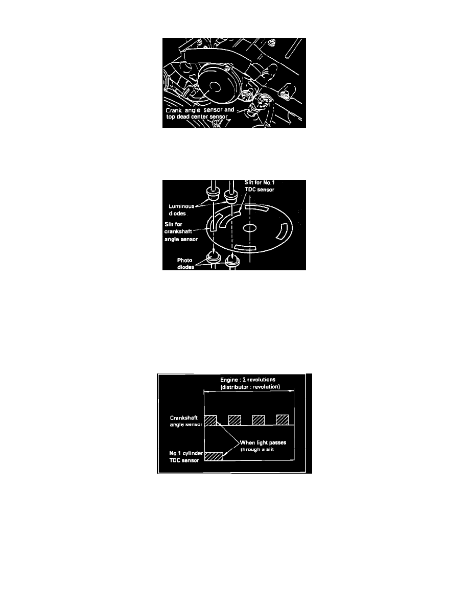
Crank-Angle And Top Dead Center Sensor
The Crank Angle Sensor and the Top Dead Center Sensor are located within the unit housing. These sensors are incorporated into one unit, and consists
of a disc and a pick-up unit. The disc is affixed to the main shaft and the light-transmitting unit is mounted stationary in the housing.
Crank Angle And #1 TDC Sensor
The disc contains 4 large slits around its circumference to indicate the crankshaft angle. An additional light-transmission slit located inward from the
edge is used to indicate number one cylinder's top dead center position. The pick-up unit assembly uses two luminous diodes and two photo diodes, in
order to detect the two different slits. There is a very slight clearance between the luminous diodes and the photo diodes, and the disc rotates within this
space.
As the main shaft rotates the slits at the discs edge pass between the light and the optical reading part of the unit. The light emitted from the luminous
diodes passes through the slits to the photo sensing diodes. When the photo diodes receive the light, they become conductive and generate a signal,
which is sent to the Control Unit.
Photoelectric Signal Pattern
No.1 Cylinder TDC Signal:
Top dead center is detected by the signal obtained through the one inner slit of the disc. The MPI controller, based upon this signal, determines which of
the four pulses from crank angle sensor is the signal for the #1 cylinder.
Crankshaft Angle Signal:
The four slits located at the outer circumference of the disc serve to detect the position of the crankshaft (and, therefore, the piston) relative to top dead
center. The MPI controller, based on this signal, determines the fuel injection timing, and also monitors the amount of intake-air, the timing of the
ignition signal, etc. for each revolution of the engine.