
Summit L4-1795cc 1.8L SOHC (1995)
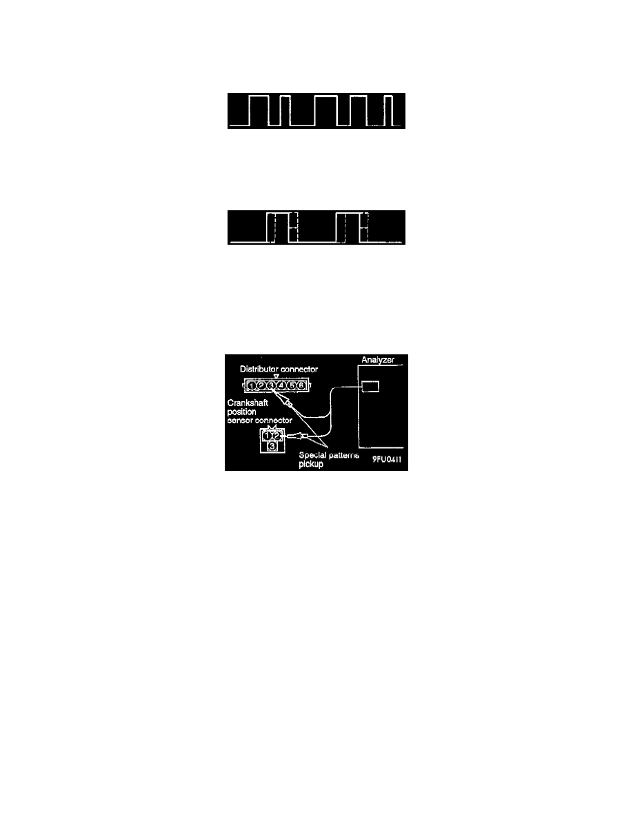
STANDARD WAVE PATTERN
Wave pattern observation points: Check to be sure that cycle time T becomes shorter when the engine speed increases.
EXAMPLES OF ABNORMAL WAVE PATTERNS
Example 1
Cause of problem - Sensor interface malfunction
Wave pattern characteristics - Rectangular wave pattern is output even when the engine is not started.
Example 2
Cause of problem - Loose timing belt, Abnormality in sensor disk
Wave pattern characteristics - Wave pattern jumps to the left or right.
With California Emissions
WAVE PATTERN INSPECTION USING AN ANALYZER MEASUREMENT METHOD
1. Disconnect the connector of the distributor and connect the special tool (test harness: MB991 348) across the disconnected connector parts.
(Connect the tool to all terminals.)
2. Connect the special patterns pick-up of the analyzer to the terminal 3 of the distributor connector (in order to inspect the signal waveform of the
camshaft position sensor).
3. Disconnect the connector of the crankshaft position sensor, and connect the special tool (test harness: MD998478) across the disconnected
connector parts.
4. Connect the special patterns pick-up of the analyzer to the terminal 2 of the crankshaft position sensor connector (in order to inspect the signal
waveform of the crankshaft position sensor).
ALTERNATE METHOD (TEST HARNESS NOT AVAILABLE)
1. Connect the analyzer special patterns pickup to ECM terminal 88 (When inspecting the camshaft position sensor signal wave pattern.)
2. Connect the analyzer special patterns pickup to ECM terminal 89 (When inspecting the crankshaft position sensor signal wave pattern.)