
Summit Vista FWD L4-1795cc 1.8L SOHC (1992)
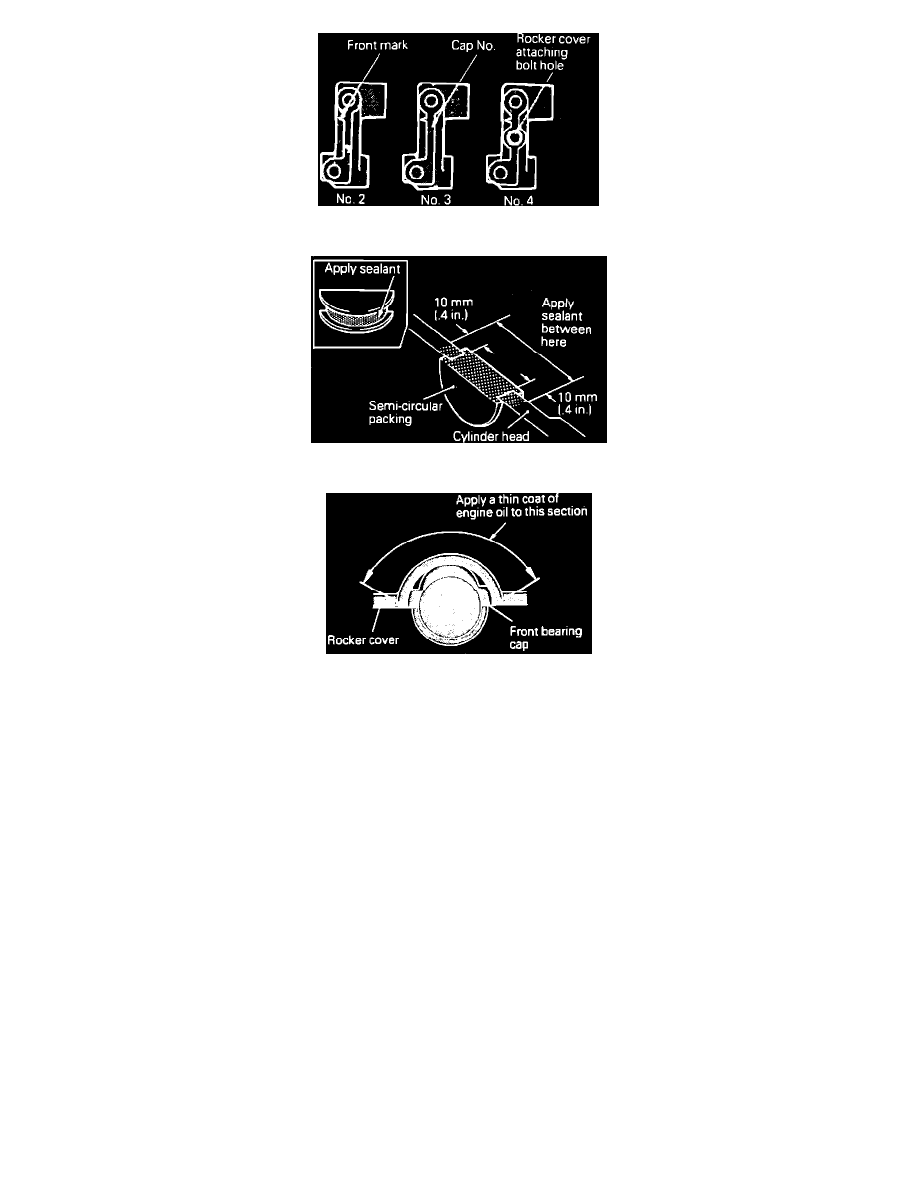
Fig. 14 Camshaft Bearing Cap Nos. 2, 3 & 4 Identification
Fig. 15 Semi-circular Gasket Installation
Fig. 16 Rocker Arm Cover Installation
1.
Disconnect battery ground cable.
2.
Remove breather hose and PVC. hose from rocker cover.
3.
Remove rocker cover, then the gasket.
4.
Rotate crankshaft in normal direction of rotation until No. 1 cylinder is at top dead center and camshaft and crankshaft timing marks are aligned.
5.
Place a chalk mark between timing belt and camshaft sprocket, then remove camshaft sprocket bolt, separate sprocket from camshaft, leaving belt
in place on sprocket. Secure sprocket and belt with wire, Fig. 2. Ensure sprocket does not disengage from belt and fall, and maintain tension on
belt to maintain proper timing.
NOTE: Do not rotate crankshaft after sprocket is removed from camshaft.
6.
Prior to removal of rocker arm and rocker shaft assembly, install hydraulic lash adjuster holder tool No. MD998443 or equivalent, to ensure the
hydraulic lash adjuster is not allowed to fall.
7.
Remove semicircular packing, then the oil seal.
8.
Remove rocker arm and shaft assembly, then the hydraulic lash adjuster.
9.
Remove camshaft.
10.
Reverse procedure to install, noting the following:
a. Assemble rocker arms to rocker shafts, then install on cylinder head, Fig. 12.
b. Apply engine oil to inside diameter of rocker before assembly.
c. Ensure cuts on rocker arm shafts are facing upward, Fig. 13. Refer to Fig. 14, for identification of Nos. 2, 3 and 4 bearing caps.
d. Apply suitable sealer to semi-circular packing, Fig. 15.
e. When valve cover is installed, apply suitable gasket sealant, Fig. 16.