
Summit Vista FWD L4-1795cc 1.8L SOHC (1992)
Seat Belt Motor: Testing and Inspection
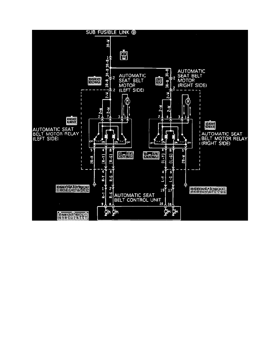
Motor Power Supply & Drive Circuit Test
Seat Belt Motor Power Supply And Drive Circuit Diagram
1.
Disconnect motor relay harness connector.
2.
Connect a suitable ohmmeter between motor relay connector terminals 1 and 3 (motor relay side).
3.
Ohmmeter should indicate continuity.
4.
If continuity is indicated, circuit is satisfactory. Proceed to step 6.
5.
If continuity is not indicated, replace motor and track assembly.
6.
Connect ohmmeter between motor relay connector terminal 5 (harness side) and ground.
7.
Ohmmeter should indicate continuity.
8.
If continuity is indicated, circuit is satisfactory. Proceed to step 10.
9.
If continuity is not indicated, repair harness as necessary.
10.
Disconnect control unit harness connector.
11.
Connect ohmmeter between motor relay connector terminal 1 (motor relay side) and ground, then between terminal 3 (motor relay side) and
ground.
12.
Ohmmeter should indicate continuity.
13.
If continuity is indicated, circuit is satisfactory. Proceed to step 15.
14.
If continuity is not indicated, replace motor and track assembly.
15.
Connect a suitable voltmeter between motor relay connector terminal 2 (harness side) and ground, then between terminal 6 (harness side) and
ground. Repeat test using terminals 2 and 7 to test left motor relay.
16.
Voltage indicated should be approximately 12 volts.
17.
If voltage indicated is as specified, circuit is satisfactory. Proceed to step 19.
18.
If voltage indicated is not as specified, repair harness as necessary.
19.
Connect motor relay harness connector.
20.
Connect voltmeter between control unit connector terminals 8, 9 and ground (left side), then between terminals 18, 19 and ground (right side).