
Summit Wagon AWD L4-1795cc 1.8L SOHC (1994)
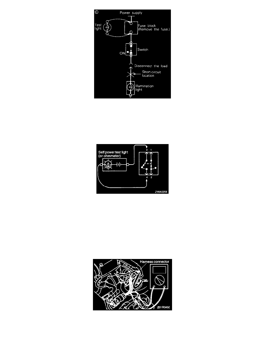
Short Circuits Check (C)
Figure C
Continuity Check
Foreword
A circuit consists of the power supply, switch, relay, load, ground, etc. There are various methods to check a circuit including an overall check,
voltage check, short circuit check and continuity check.
Continuity Check
Continuity Check
a. When the switch is in the OFF position, the self power test light should come on or the ohmmeter should read 0 Ohm only when the terminals 1
and 2 are interconnected.
b. When the switch is in the ON position, the self power test light should come on or the ohmmeter should read 0 Ohm only when the terminals 3 and
4 are interconnected.
Connector Continuity and Voltage Tests
When checking continuity and/or voltage at the waterproof connectors, follow the steps below to avoid poor connector contact and/or reduced
waterproof performance of connectors.
Connector Continuity And Voltage Test
1. When checking is performed with the circuit in the state of continuity, be sure to use the special tool (harness connector). Never insert a test bar