
Summit Wagon AWD L4-1795cc 1.8L SOHC (1994)
Voltage Check
Voltage Check
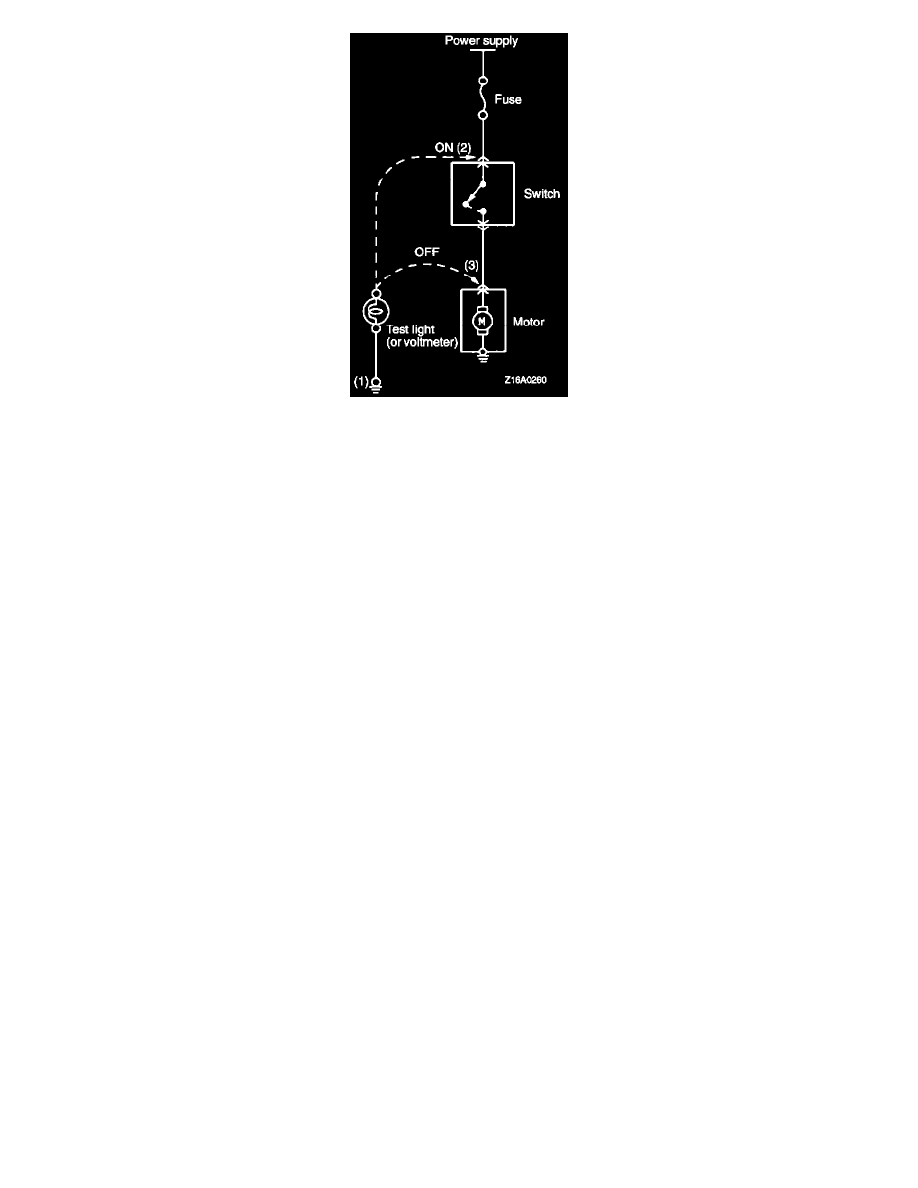
1. Ground one lead wire of the test light. If a voltmeter is used instead of the test light, ground the grounding side lead wire.
2. Connect the other lead wire of the test light to the power side terminal of the switch connector. The test light should come on or the voltmeter
should indicate a voltage.
3. Then, connect the test light or voltmeter to the motor connector. The test light should not come on, or the voltmeter should indicate no voltage.
When the switch is turned on in this state, the test light should come on, or the voltmeter should indicate a voltage, with motor starting to run.
4. The circuit illustrated here is normal but if there is any problem such as the motor failing to run, check voltages beginning at the connector nearest
to the motor until the faulty part is identified.
Short Circuit Check
Foreword
A circuit consists of the power supply, switch, relay, load, ground, etc. There are various methods to check a circuit including an overall check,
voltage check, short-circuit check and continuity check. Each of these methods is briefly described.